Background
I’ve been fascinated by high-volume, fault-tolerant data storage systems for a long time. I started my data storage setup in earnest with a 4-disk RAID 5 array on an ARC-1210 controller installed in my daily-driver Windows desktop. When that array inevitably filled up, I added another array on a second ARC-1210. That slowly filled up, too, and I knew I couldn’t just keep stuffing RAID cards in my desktop; I had to build a serious file storage server eventually.
I considered many different storage options and configurations, including a large hardware-controlled RAID system on a Windows or Linux environment, a software-controlled array in a Windows-based server, a Drobo-type “keep it simple, stupid” system, and continuing to simply add more drives to my desktop computer. None of these options seemed to address all my requirements very well. I eventually stumbled upon FreeNAS, a FreeBSD-based, network storage oriented operating system that uses the ZFS file system and a web interface to configure network sharing and other settings. While most of the setup and system management is done through this web interface, but you can extend the machine’s capabilities quite a bit through the terminal via SSH. In this article, I’ll go over my hardware selections, the build and configuration process, some of the other applications I have running on the machine, and a bit of theory about how ZFS allocates array storage space and how it can be tuned to reduce allocation overhead.
I want to make a quick note before diving into this excessively long article. I started writing the first few sections intending to create a detailed build log for my server. I took pictures and documented every step as well as I could; I had been planning this server over the span of several years, so I was understandably excited to get into it. As the article progressed, it started to shift into a combination of a build log and a tutorial. While the exact set of parts and the sequence of their assembly and configuration will likely be fairly unique to the machine I built, I hope that people undertaking a similar project will find helpful information in some portion of this article. My contact information is at the bottom of this article if you would like to get in touch with me for any reason.
[2017 Update:] I've had this server for a little over a year now and have made several changes to the configuration. Those changes include the following:
- Putting the sever in a proper rack
- Getting an NVMe SSD for virtual machines
- Installing another 8 drives in the front bays (along with another M1015)
- Installing an internally-mounted "scratch disk"
- Creating a front fan shroud for 3x 140mm fans to increase cooling performance
[2018 Update:] The server has been going strong for two years now. I've made some more changes to the system in the past year:
- Upgrading to 10GbE copper networking
- Replacing the internal "scratch disk" with 2x 2TB SATA SSDs shared via iSCSI
[2019 Update:] Three years! I've made some major changes this year to support the addition of a second 24-bay chassis:
- Replaced 3x M1015 cards with 1x LSI 9305-24i HBA
- Added external SAS HBA to support expansion chassis, LSI 9305-16e
- Added second 846 chassis for expansion
- Added 16 new 8TB HDDs
- Overhauled the fan control setup to support more fan zones
- Upgraded memory to 128 GB
- Added a second UPS to handle the increased power load
- Added a 280GB Optane 900p for an L2ARC
- Added cable management arms
- Added external display to show live system temperature and fan speed data
[2020 Update:] I made a few minor upgrades through 2020:
- Added 8x 8TB disks to fill the second chassis
- Replaced all the 4TB disks with 8TB disks (several 4TB disks had failed)
- Replaced the CPU with a Xeon E5-2666 v3 (10C/20T @ 2.9GHz)
- Removed all the VM/bhyve stuff from the FreeNAS system and moved it onto a dedicated Proxmox host
[2021 Update:] I added another expansion shelf in 2021:
- Added a 36-bay SC847 chassis (24 bays in front, 12 in rear)
- Added 34x 8TB disks (4x additional 8-wide Z2 vdevs and 2 spares)
- Added 2x 2TB SSDs to the scratch disk pool
- Replaced the original 1500VA UPS
I've made updates to the original text to reflect these changes, marking paragraphs as updated where appropriate. The system summary section just below will always include whatever the latest configuration is. There are places where I've included original text from the article even though it's no longer applicable to my build; I've done so because in these cases, the old might be helpful (for example, info on preparing the Ikea LACK table to hold the server).
Contents:
- Background
- System Summary
- Photos
- Parts and Price List
- Parts Selection Details
- Build Process
- Flashing the M1015 HBA Cards & Installing FreeNAS
- Initial FreeNAS Configuration
- Calculating & Minimizing ZFS Allocation Overhead
- Setting Up Storage Volumes
- Further System Configuration
- Setting Up SMB Sharing
- Adjusting Permissions
- Setting Up iSCSI Sharing [2018 Update]
- Performing Initial bhyve Configuration
- Creating a bhyve VM
- Configuring rclone in a bhyve
- Expanding Beyond a Single Chassis [2019 Update]
- Closing and Summary
System Summary
The server is running on FreeNAS 12.0 with 6x 8-drive RAID-Z2 virtual devices (vdevs) with 8TB disks for a total of ~250 TB of usable, redundant space. These drives in the main chassis (or "head unit") are connected to an LSI 9305-24i. The drives in the second chassis (or "expansion shelf") are connected with an LSI 9305-16e and a SAS3 expander backplane. The boot volume is stored on 2x mirrored Intel 540s 120 GB SSDs. I have an internally-mouted pair of 2 TB SATA SSDs striped together for ~4TB of fast, temporary data storage. The head unit is housed in a SuperMicro SC846 chassis with two 920W redundant PSUs; the expansion has the same. The system is built on a SuperMicro X10SRL-F LGA2011-v3 motherboard. I’m using an Intel Xeon E5-2666 v3 (10C/20T @ 2.9GHz) and 8 modules of 16GB DDR4 Samsung ECC/registered memory for a total of 128GB of RAM. I’m using a Noctua cooler on the CPU and I replaced the noisy stock chassis fans with quieter Noctua fans. I also created a front fan shroud that holds 3x 140mm fans to increase cooling while keeping noise levels down. I have one mounted on both the head unit and the expansion shelf. I have two APC 1500VA Smart-UPSs and have them and the file server in a 42U Dell rack cabinet from Craigslist.
I set my primary dataset with recordsize = 1MiB to account for data block placement in an 8-drive Z2 array. Most of the data is shared via SMB/CIFS. I also have an iSCSI share on the main pool mounted on my desktop for my Steam library, and an iSCSI share on the mirrored SATA SSDs mounted in one of the VMs (and then reshared via SMB). The system hosts several different Debian-based bhyve VMs to run various services I use on a day-to-day basis (including nginx, pi-hole, irssi, an OpenVPN server, and an rclone client I use to back up my data to ~~the cloud~~). I have scripts set up to send SMART and zpool status reports to my email address on a weekly basis and scrubs/SMART checks scheduled every 2 weeks. I also have a script that automatically adjust the chassis fan speeds based on live HDD and CPU temps.
The fan control for each chassis is now handled through Raspberry Pis that output the appropraite PWM signal. I still have the script running on the FreeNAS system to monitor drive temperatures, but now instead of setting fan speeds by sending ipmitool commands, it sends the commands to the Raspberry Pi systems in each chassis via Python's sockets module. The Pis also measure fan speed and ambient chassis temperature which is all sent to another Pi running a webserver with flask, socket.io, and redis that displays lots of system vitals.
Of course the primary purpose of the NAS is data storage. The vast majority of the data I store is from the high-resolution photography and videography I've done over the past 10-15 years, most of which is stored in some sort of raw format. I could probably go through and delete about 95% (even 99%) of the data, but I would rather keep everything around so I can pretend that maybe some day, someone will be interested in looking at them (maybe I'll have very patient kids?). I look at this use case as a modern version of the boxes full photo albums and slides my parents and grandparents kept in their basement for decades and never looked at. Even if no one ever looks at my pictures and videos, it's still be a really fun project to work on. By the way, if you're interested in looking at some of my favorite photographs, you can find them here!
Photos
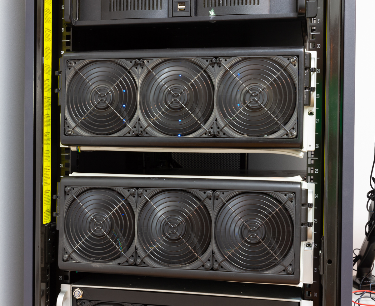
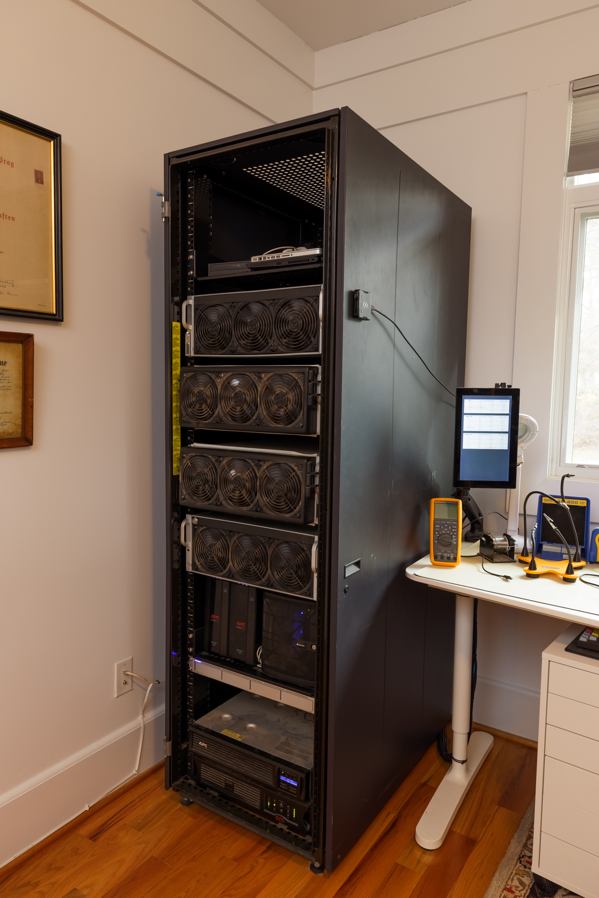
The front of the server with the front fan shroud on. The top chassis is the head unit, the lower chassis is the expansion shelf.
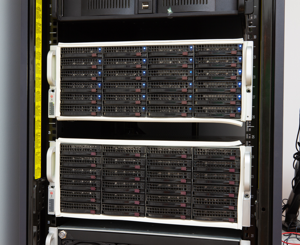
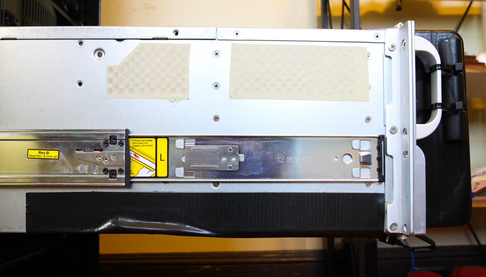
The front of the server with the front fan shroud removed (note the weather stripping tape around the edges).
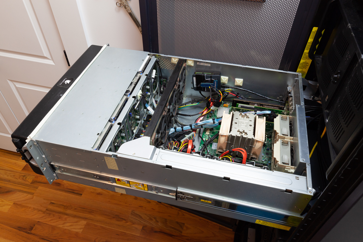
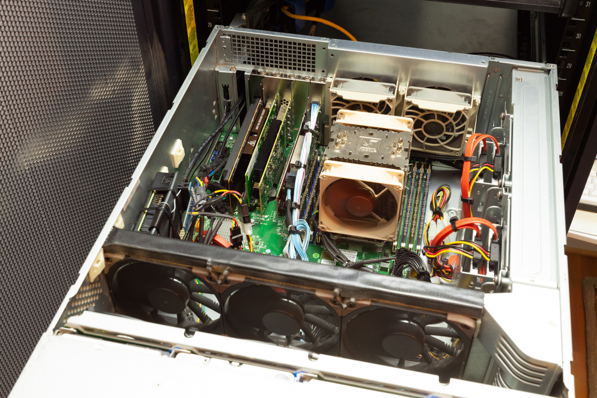
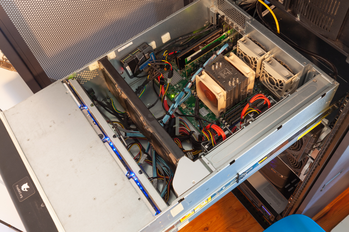
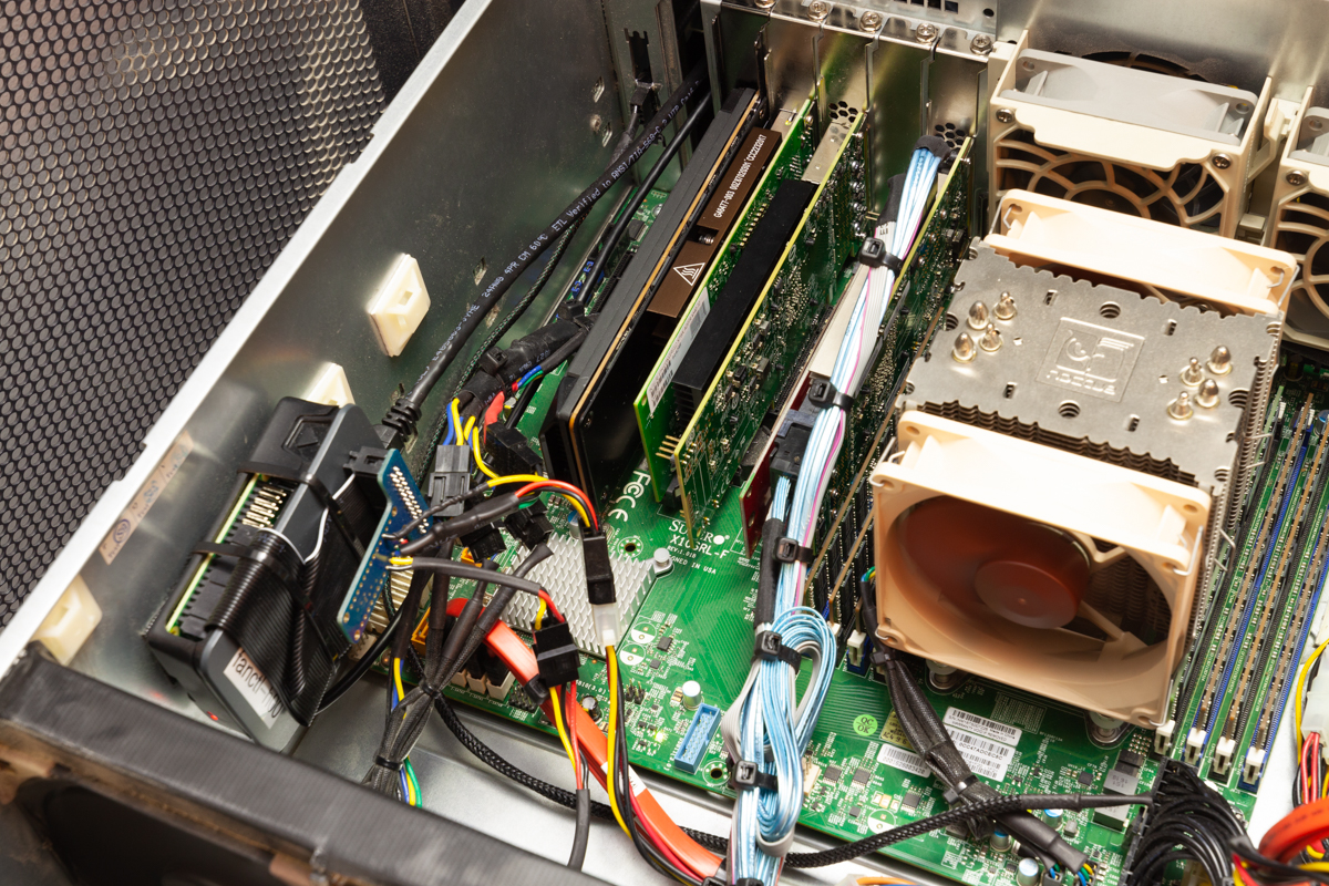
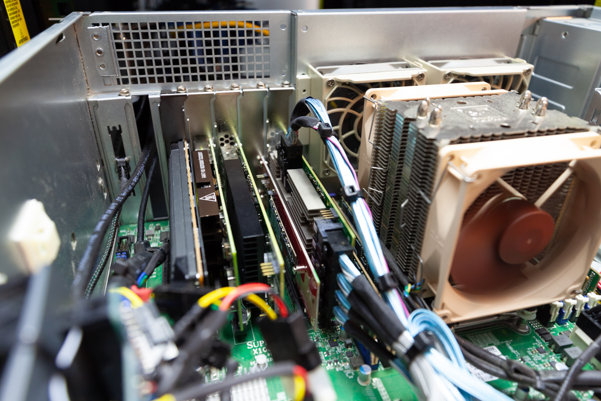
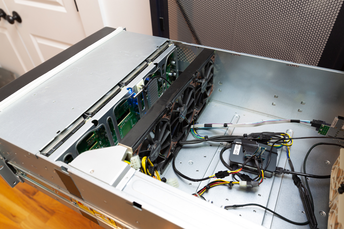
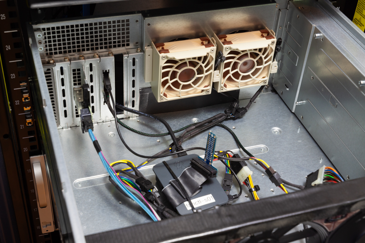
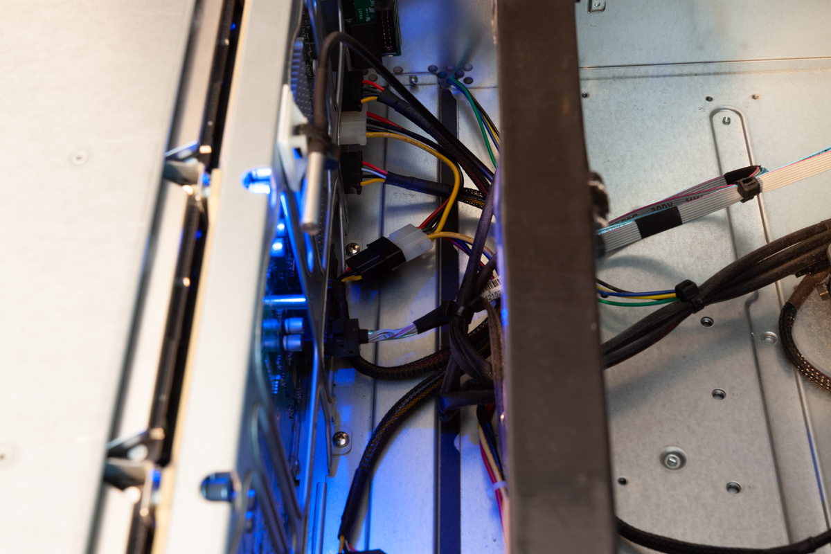
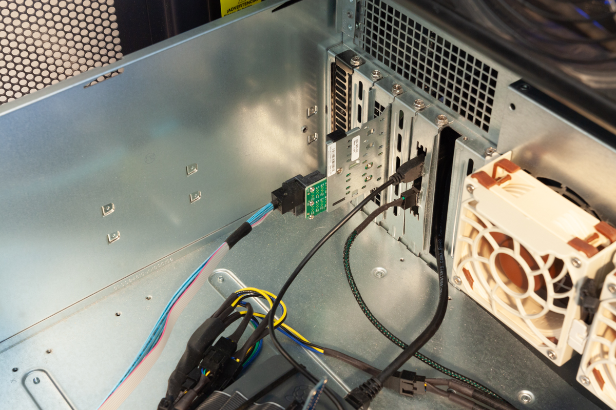
A few different views of the inside of the head unit.
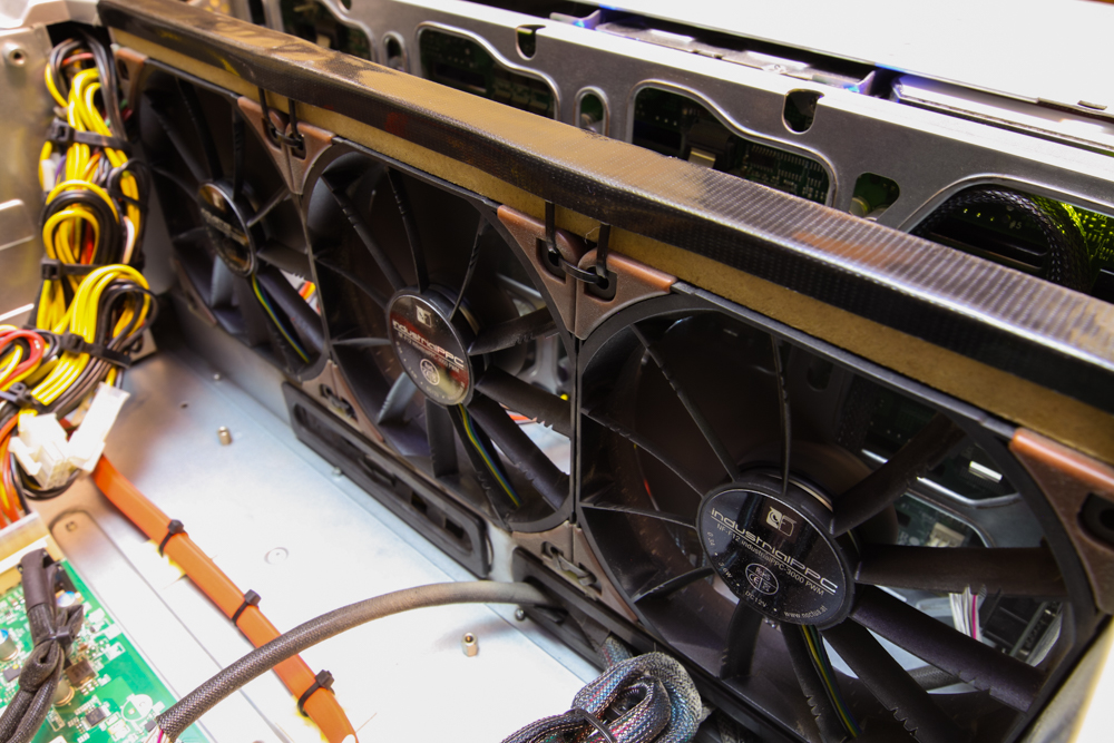
A view of the fan wall, secured with zip ties. The strip on top of the fan wall helps to seal off the two sections of the chassis, making sure air flows through the drive bays rather than back over top of the fan wall.
Inside of the expansion shelf chassis.
All expansion shelf drives connected via a single SAS3 cable.
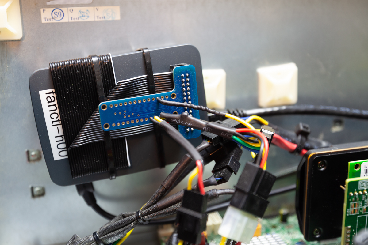
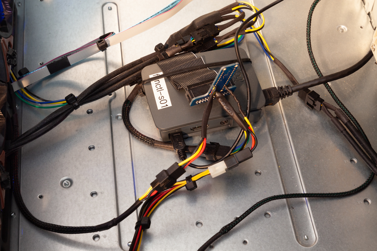
The fan control Raspberry Pi in the head unit and in the shelf.
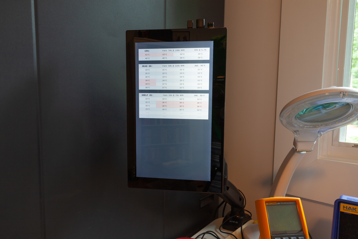
The dedicated 11" display for system stats, including drive temperatures, ambient chassis temp, CPU temp and load, and fan speeds.
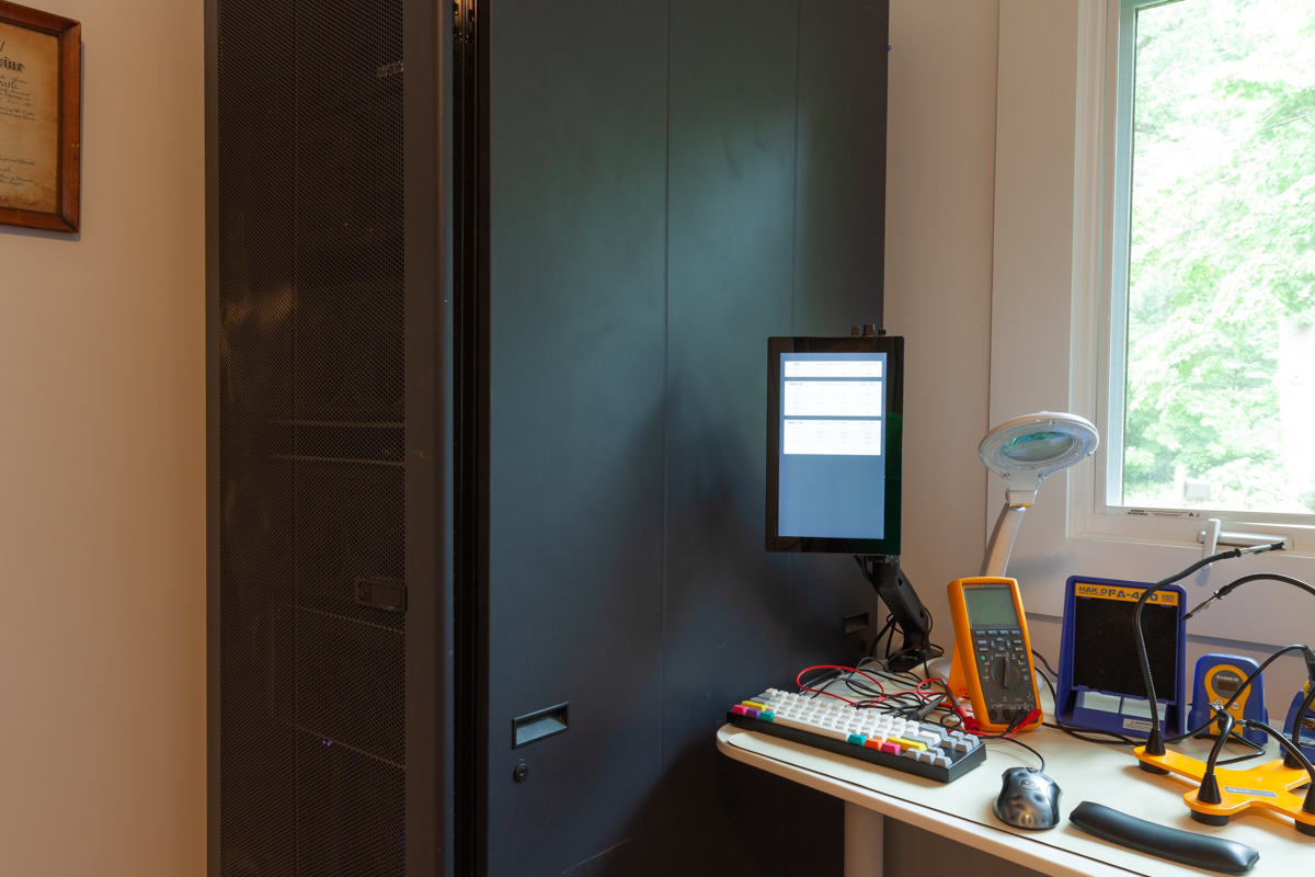
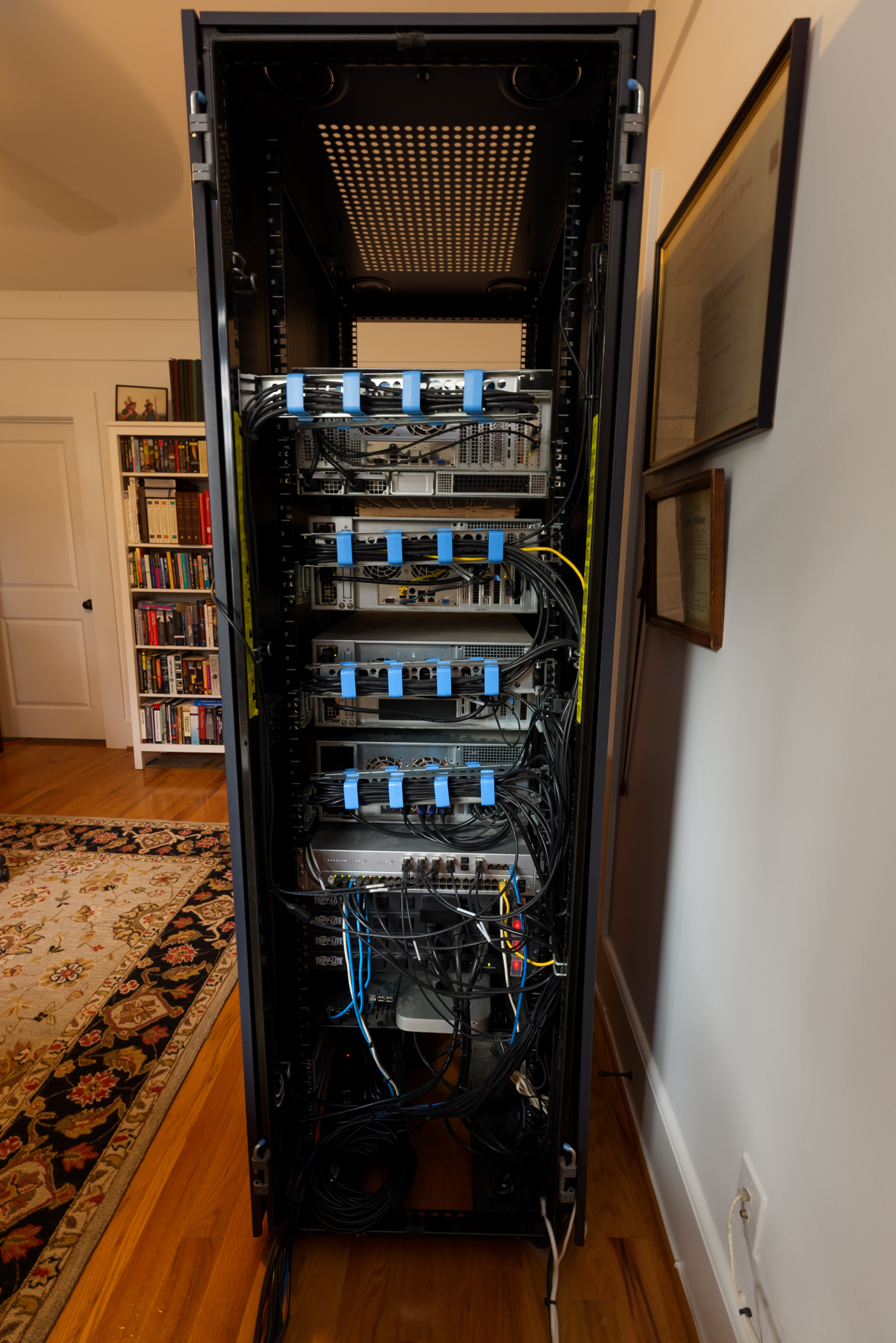
A view of the front and back of the rack. From top to bottom, I have my Proxmox server, the FreeNAS head unit, the expansion shelf, my new workstation, a FreeNAS mini, a UniFi NVR, and some UPSs.
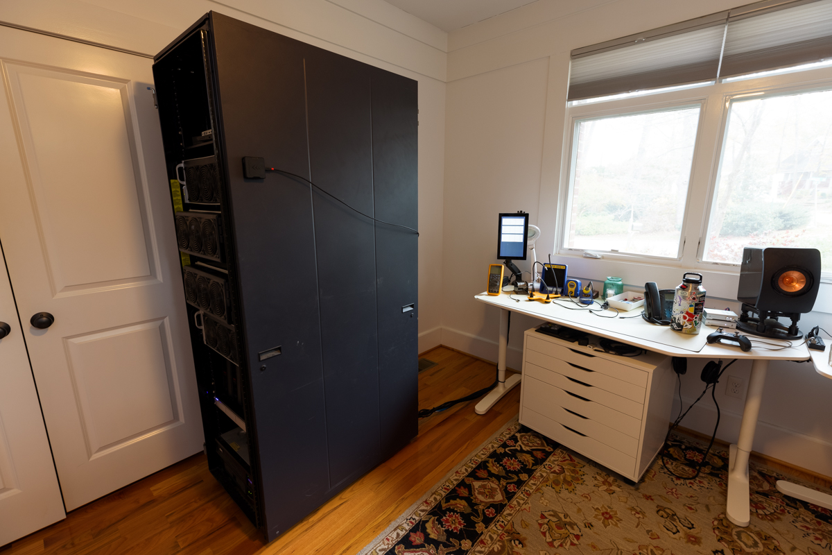
The whole rack rolls out several feet so I can get behind it when needed.
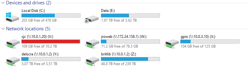
Here is a screenshot of the mounted shares.
Parts and Price List
[2019 Update:] Now that the system has gone through so many changes, I've decided to restructure this table to group things based on the yearly upgrades. Parts that have been functionally replaced in a later upgrade will be marked with strikethrough text. These replaced parts are still included in the price totals.
| Part | Make/Model | Qty | $ Per | $ Total | From |
|---|---|---|---|---|---|
| Original Build (2016) | |||||
| Chassis | SuperMicro SC846 | 1 | $200 | $200 | TheServerStore |
| Motherboard | SuperMicro X10SRL-F | 1 | $272 | $272 | Amazon |
| RAM | Samsung M393A2G40DB0-CPB (16GB) | 4 | $80 | $320 | Amazon |
| PSU | SuperMicro PWS-920P-SQ | 2 | $118 | $236 | eBay |
| Backplane | SuperMicro BPN-SAS-846A | 1 | $250 | $250 | eBay |
| Data Drive | WD 8 TB Red (8 + 1 Spare) | 9 | $319 | $2,871 | Amazon |
| Data Drive | WD 4 TB Red (Already Owned) | 8 | $0 | $0 | - |
| Boot Device | Intel 540s 120GB SSD | 2 | $53 | $105 | Amazon |
| CPU Cooler | Noctua NH-U9DXi4 | 1 | $56 | $56 | Amazon |
| 120mm Fan | Noctua NF-F12 iPPC 3000 PWM | 3 | $24 | $72 | Amazon |
| 80mm Fan | Noctua NF-R8 PWM | 2 | $10 | $20 | Amazon |
| UPS | APC SUA1500RM2U Smart-UPS | 1 | $300 | $300 | eBay |
| SAS Cable | SFF-8087 to SFF-8087 | 4 | $11 | $44 | Amazon |
| HDD Screws | SuperMicro HDD Screws (100 ct) | 1 | $8 | $8 | Amazon |
| Tax, Misc. Cables, etc. | Tax, misc. | 1 | $250 | $250 | - |
| SSD Cage | SuperMicro MCP-220-84603-0N | 1 | $25 | $25 | eBay |
| Original System Total: | $5,528 | ||||
| 2017 Update | |||||
| Data Drive | WD 8 TB Red (from WD EasyStore) | 8 | $130 | $1,040 | Best Buy |
| Front Fan Shroud | (3D Printed PLA) | 1 | $180 | $180 | 3DHubs |
| 140mm Fan | Noctua NF-A14 iPPC 3000 PWM | 3 | $25 | $75 | Amazon |
| Rack Cabinet | Dell 42U | 1 | $300 | $300 | Craigslist |
| Server Rails | Supermicro MCP-290-00057-0N | 1 | $75 | $75 | eBay |
| 2017 Update Total: | $2,207 | ||||
| 2018 Update | |||||
| 10GbE NIC | Intel X540T2 | 1 | $248 | $248 | Amazon |
| SSD Cage | SuperMicro MCP-220-84603-0N | 1 | $25 | $25 | eBay |
| SSD Scratch Disks | Micron MX500 2 TB | 2 | $339 | $678 | Amazon |
| 2018 Update Total: | $976 | ||||
| 2019 Update | |||||
| Data Drive | WD 8 TB Red (from WD EasyStore) | 16 | $130 | $2,080 | Best Buy |
| Expansion Chassis | SuperMicro SC846 | 1 | $250 | $250 | TheServerStore |
| Expansion PSU | SuperMicro PWS-920P-SQ | 2 | $100 | $200 | TheServerStore |
| Server Rails | Supermicro MCP-290-00057-0N | 1 | $100 | $100 | TheServerStore |
| Expansion Backplane | SuperMicro BPN-SAS3-846EL1 | 1 | $630 | $630 | eBay |
| Additional RAM | Samsung M393A2G40DB0-CPB (16GB) | 4 | $151 | $604 | Newegg |
| L2ARC Drive | Intel Optane 900P 280GB AIC | 1 | $133 | $133 | Amazon |
| Internal HBA | LSI SAS 9305-24i | 1 | $570 | $570 | Amazon |
| External HBA | LSI SAS 9305-16e | 1 | $550 | $550 | Amazon |
| Front Fan Shroud | (3D Printed PLA) | 1 | $180 | $180 | 3DHubs |
| 140mm Fan | Noctua NF-A14 iPPC 3000 PWM | 3 | $25 | $75 | Amazon |
| 120mm Fan | Noctua NF-F12 iPPC 3000 PWM | 3 | $24 | $72 | Amazon |
| 80mm Fan | Noctua NF-R8 PWM | 2 | $10 | $20 | Amazon |
| SAS Ext. to Int. Adapter | Supermicro AOM-SAS3-8I8E | 1 | $80 | $80 | Supermicro Store |
| SAS3 Ext. Cable | SuperMicro CBL-SAST-0573 | 1 | $60 | $60 | Supermicro Store |
| SAS3 Int. Cable | SuperMicro CBL-SAST-0593 | 1 | $15 | $15 | Supermicro Store |
| SAS3 to SAS2 Cable | SuperMicro CBL-SAST-0508-02 | 6 | $13 | $78 | Supermicro Store |
| Cable Management Arm | SuperMicro MCP-290-00073-0N | 2 | $56 | $112 | Supermicro Store |
| UPS | APC SUA1500RM2U Smart-UPS | 1 | $300 | $300 | eBay |
| Dual PSU Adapter | Generic Amazon Model | 1 | $7 | $7 | Amazon |
| Rasp. Pi + SD Card | RPi Model B+, 32GB MicroSD Card | 3 | $45 | $135 | Amazon |
| Thermal Probes | Aideepen 5pc DS18B20 | 1 | $12 | $12 | Amazon |
| System Vitals Display | 11" 1080p Generic Touchscreen | 1 | $159 | $159 | Amazon |
| Arm for Display | VIVO VESA Arm | 1 | $32 | $32 | Amazon |
| 2019 Update Total: | $6,454 | ||||
| 2020 Update | |||||
| Data Drive | WD 8 TB Red (from WD Elements) | 13 | $130 | $1,690 | B&H |
| CPU | Intel Xeon E5-2666 V3 | 1 | $190 | $190 | eBay |
| 2020 Update Total: | $1,880 | ||||
| 2021 Update | |||||
| Data Drive | WD 8 TB Red (from WD EasyStore) | 34 | $140.00 | $4,760.00 | Best Buy |
| Expansion Chassis | Supermicro SC847 | 1 | $701.00 | $701.00 | TheServerStore |
| Front Backplane | Supermicro BPN-SAS3-846EL1 | 1 | - | - | TheServerStore |
| Rear Backplane | Supermicro BPN-SAS3-826EL1 | 1 | - | - | TheServerStore |
| PSUs | Supermicro PWS-1K28P-SQ | 2 | - | - | TheServerStore |
| Rails | Supermicro MCP-290-00057-0N | 1 | - | - | TheServerStore |
| SAS3 Int. Cable | SuperMicro CBL-SAST-0593 | 2 | - | - | TheServerStore |
| Front Fan Shroud | (3D Printed PLA) | 1 | $339.00 | $339.00 | 3DHubs |
| SAS3 Ext. Cable | Supermicro CBL-SAST-0677 | 2 | $90.00 | $180.00 | eBay |
| SAS Ext. to Int. Adapter | Supermicro AOM-SAS3-8I8E | 1 | $45.00 | $45.00 | eBay |
| 140mm Fan | Noctua NF-A14 iPPC 3000 PWM | 3 | $28.00 | $84.00 | Amazon |
| 120mm Fan | Noctua NF-F12 iPPC 3000 PWM | 3 | $26.00 | $78.00 | Amazon |
| 80mm Fan | NF-A8 PWM | 10 | $16.00 | $160.00 | Amazon |
| PWM Fan Splitter | 5-Way Fan Hub | 2 | $7.00 | $14.00 | Amazon |
| PSU Adapter | Thermaltake Dual 24-Pin | 1 | $11.00 | $11.00 | Amazon |
| 2.5" Tray Adapter | Supermicro MCP-220-00118-0B | 2 | $24.00 | $48.00 | eBay |
| SSD Scratch Disks | Micron MX500 2 TB | 2 | $200.00 | $400.00 | Amazon |
| Cable Management Arm | SuperMicro MCP-290-00073-0N | 1 | $56.00 | $56.00 | Supermicro Store |
| Replacement UPS | APC SMT1500RM2U | 1 | $230.00 | $230.00 | eBay |
| UPS Battery Pack | APC APCRBC133 | 1 | $260.00 | $260.00 | APC Store |
| 2021 Update Total: | $7,366 | ||||
| Grand Total: | $24,411 | ||||
Parts Selection Details
My primary objectives when selecting parts were as follows:
- Allow for up to 24 drives,
- Be able to saturate a gigabit ethernet line on SMB/CIFS
- Have a quiet enough system that it can sit next to me in my office
Redundancy and overall system stability were also obvious objectives and led me to select server-grade components wherever appropriate. Here’s a breakdown of the reasoning behind each part I selected:
Chassis: SuperMicro SC846 – I purchased this used on eBay for $200 shipped. It retails for close to $1000, so it’s a pretty good deal. I considered the Norco RPC-4224 for a while, but the SuperMicro chassis is much higher quality and has better thermal design (i.e. bottomless HDD sleds for better airflow). The specific chassis I purchased came with an older version of the SC846 backplane that doesn’t support larger-capacity volumes, so I had to buy a different backplane. The PSUs the chassis came with are really loud, so I purchased some quieter ones. The stock system fans are also loud, so I replaced those too. More information on the replacement backplane, PSUs, and fans below. I currently have 8 open drive bays to allow for future expansion. [2019 Update:] For my big system expansion, I picked up a second 846 chassis on eBay. More details on this expansion are below.
Motherboard: SuperMicro X10SRL-F – This is SuperMicro’s basic LGA2011 server board. An LGA1151-based board would have worked
but the SC846 chassis doesn’t have mounting holes for micro ATX boardsand the full ATX versions of SuperMicro’s LGA1151 boards are very expensive (Update: apparently the 846 does have micro ATX mounting holes, so I could have saved a fair bit of coin there. Oh well... thanks /u/techmattr on reddit for pointing this out.) LGA2011 will also allow me to add more RAM if I ever need to.CPU: Intel Xeon E5-1630v3 – With 4 cores/8 threads at 3.7GHz, this has the highest single core clock speed in this family of Xeons, which is really nice for SMB/CIFS. I had to get it on SuperBiiz because it’s typically only sold to systems integrators, but it was a painless experience despite my initial misgivings. [2020 Update:] The old 4C/8T Xeon was not happy during scrubs with 48 disks on the system. I picked up an E5-2666 V3 to replace it, with is a custom Amazon SKU that I found for a very reasonable price on eBay.
RAM: Samsung M393A2G40DB0-CPB (4x16GB, 64GB total) – This is one of the SuperMicro-recommended RAM models for the X10SRL-F motherboard; all the other models are really hard to find. I went with ECC RAM because scary cosmic radiation (and because the FreeNAS community convinced me ECC was an absolute requirement). See this interesting article on more information on ZFS and the supposed dire need for ECC RAM. The RAM is also registered/buffered because the DIMM size is so large. 64GB is on the high side, but 32GB is the next step down and that would have been cutting it close. I shouldn't have to add more RAM when I eventually fill the last 8 HDD bays in my chassis [2019 Update:] I added another 64GB of RAM to support the expansion, bringing the total to 128GB.
Host Bus Adapter (HBA): IBM M1015 – These cards are flashed to IT mode so the FreeNAS OS has direct access to the drives for SMART data, etc. Each card handles 8 drives and I’ve got room for another card if (see: when) I need to populate the last 8 bays in the chassis. [2017 Update:] The time for another 8 drives came after all! I picked up a 3rd M1015 when I got my new drives. [2019 Update:] As part of the system expansion, I needed to consolidate PCIe cards. Part of that consolidation was replacing the 3x M1015's with a single LSI 9305-24i which can handle all 24 of the head-unit drives via my direct attach backplane. For the expansion shelf, I added an LSI 9305-16e. It's connected to an expander-based backplane in the shelf, so a single one of the HBA's four ports can handle all 24 drives in the shelf.
Data Drives: Western Digital Red (4TB & 8TB) – I was already running the 8x 4TB drives in my desktop, so I initially built the NAS around 8x 8TB drives, moved the data from the 8x 4TB drives in my desktop to the NAS, then moved the 8x 4TB drives into the NAS and expanded the pool. I bought a spare drive in 4TB and 8TB to have on hand in case of a failure. People like WD Red for NAS, but HGST would have been a good option too. I’ve found that the 8TB WD Red drives tend to run much hotter than the 4TB WD Reds. [2017 Update:] I added 8 more WD Red 8TB drives to the pool. I got them from Best Buy's Thanksgiving sale for $130 each. They're sold as external drives (WD EasyStore), but it's pretty easy to "shuck" them to get at the drive within. Most of the drives I got have white labels on them, but they're otherwise identical to WD Reds (same RPM and capabilities). I also got a 9th drive to serve as a "scratch" disk that I installed in a mount inside the chassis. I use this drive to store data that doesn't need to be stored on the main pool with redundancy (temp files, dev/test stuff, etc). [2018 Update:] I removed the scratch disk and replaced it with a pair of 2 TB SATA SSDs; see below for details. [2019 Update:] 16 more drives added in the expansion shelf.
[2020 Update:] I added another vdev worth of disks to the expansion shelf (8x 8TB) and replaced all the remaining 4TB disks with 8TB disks. Several of the 4TB disks had failed so I only had 4 or 5 left alive in the pool. I decided it was time to replace them as the ones that were left alive had like 9 years of run time on their SMART stats. The replacement process was very painless as I had multiple free bays (I hadn't installed the 8x new 8TB disks yet). I followed the steps here and found I could run the replace operation on all the disks in parallel. After the operation had finished, my pool automatically expanded.Power Supply Unit (PSU): SuperMicro PWS-920P-SQ – These are the 920W redundant PSUs for the SC846 chassis and are much quieter than the stock 900W PSUs that came pre-installed in my SC846. I got them new/open box from eBay for $120 each. I guess the “-SQ” stands for “super quiet”? SuperMicro doesn’t state anywhere in any of their documentation or sales material that these are a quieter option; they don’t even give acoustic dB level ratings for their PSUs. I found out about these PSUs after reading user reviews on Amazon and Newegg. Whatever, they’re really quiet despite the lack of supporting marketing material. [2019 Update:] Obviously, the shelf needs power too! Got another 2 PSUs for it.
10GbE NIC: Intel X540T2 [2018 Update] – This is a 10GbE copper network interface card from Intel with 2 RJ45 ports on it. With this upgrade, I also got a matching NIC for my desktop computer and a Netgear switch with 2x 10GbE ports on it. Eventually, I want to expand the 10G capabilities of my home network to some other machines, but the gear is still pretty expensive. Note that with this 10G network card, there were all sorts of network-related tunables I had to add to FreeNAS to get everything running a full-speed. More notes on that below.
Backplane: SuperMicro BPN-SAS-846A – The SuperMicro SC846 backplane lineup is very confusing, so a high-level overview of the more common SC846 backplanes might be helpful:
BPN-SAS-846EL1 - This is the backplane that came in my server, but it’s listed as end-of-life (EOL) by SuperMicro. It has a built-in SAS expander chip but it isn’t SAS2 capable so the maximum total capacity of the array is limited (to exactly what capacity, I am not sure). In other words, you might be able to populate 24 * 2TB drives and see all 48TB, but if you try 24 * 4TB drives, it might only see 60TB. I have no idea what the actual limitations are; these numbers are purely arbitrary examples.
BPN-SAS-846A - This is the backplane I purchased. It’s basically a SAS breakout cable baked into a PCB, so no expander chip to potentially cap the total array capacity. It has 6 mini-SAS ports on the back, each of which directly connects to 4 hard drives.
BPN-SAS2-846TQ - This backplane has 24 individual SATA ports directly connected to the 24 drives on the other side of the board. It’s very simple and a decent option, but cabling can be messy. These can also be found at a reasonable price on eBay.
BPN-SAS2-846EL1 - This is the SAS2-capable expander-based backplane. This is usually reasonably priced and would have been a good option in my build, but I had a hard time finding one on eBay when I was doing all my purchasing. If it has a maximum total array capacity, it’s large enough that you shouldn’t have to worry about it. With this backplane, you would only need to use one port on a single M1015 card and the backplane would expand that single connection out for all 24 hard drives. However, this would cause a slight bottleneck with most platter drives (you would get ~24Gb/s on the SAS link, so roughly 1Gb/s or 125MB/s per drive). I’ve seen some people on forums claim that you can connect two HBA cards to this backplane to double the total bandwidth to 48Gb/s, but this is not documented anywhere by SuperMicro; they say the other two mini-SAS ports are only for cascading with other storage systems.
BPN-SAS2-846EL2 - The same as the above -846EL1, but with a second expander chip to support failing over to a redundant (set of) HBA card(s). These tend to be $600+ on eBay when you can find them.
BPN-SAS3-846EL1 & -846EL2 - The same as the above two items, but with a SAS3 capable expander chip (or 2 chips in the case of the -846EL2).
I’ll also note here the equally-confusing SC846 chassis model numbers are based on the backplane they include and their PSUs. You can double-check this by going to the product page on SuperMicro’s site and clicking “See Parts List”. [2019 Update:] For the shelf, I picked up a SAS3 expander backplane so I could attach all the drives via a single cable. BPN-SAS3-846EL1 is the model number.
Boot Device: Intel 540s 120GB SSD – This is the cheapest SATA Intel SSD I could find. People typically use USB drives for their boot device, but for a build like this, the gurus recommend using SSDs for increased system reliability. The controllers on most USB drives are pretty unreliable, so it was a worthwhile upgrade for me.
VM SSD/NVMe Adapter: Samsung 960 Pro and StarTech PCIe card [2017 Update] – When I first built this server, all my VMs were running directly on the main storage pool. When there was a lot of disk I/O going on from the network share or some other service (scrubs, SMART tests, etc.), VM performance would drop to a crawl. My solution was to pick up an NVMe SSD and migrate all the VMs to that. My motherboard doesn't have an M.2 slot, so I picked up a cheap StarTech PCIe card and it seems to work pretty well. Migrating the VMs basically involved taking a snapshot of the bhyve dataset in ZFS and restoring it to a new pool I created with the NVMe drive. I had to tinker around with some settings in iohyve to make sure everything was pointed to the right place, but it ended up being a fairly painless process. VM performance after the change improved significantly. [2020 Update:] I had been getting extremely frusterated with bhyve over the past 4 years and finally hit a breaking point. I put together a Proxmox server and moved all my VMs off the FreeNAS system. I'm planning on doing a writeup on the Proxmox build at some point, so stay tuned for that!
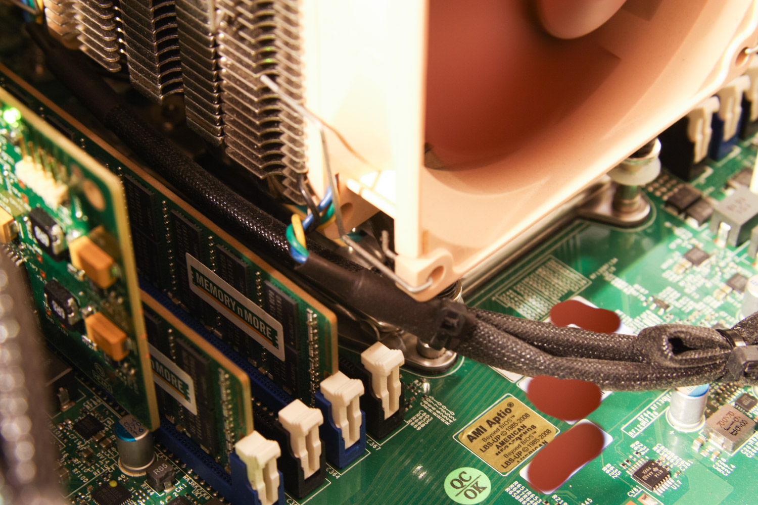
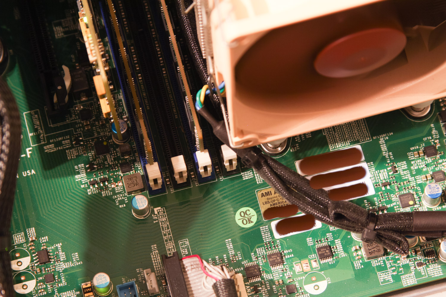
CPU Cooler: Noctua NH-U9DXi4 – This is a basic server-grade CPU cooler from the much-respected Noctua. I was initially nervous about its fit with my motherboard and chassis, but it ended up working out pretty well. While it does provide enough vertical clearance for DIMMs installed in the RAM slots closest to the CPU socket (at least with these Samsung DIMMs), it’s so close that I’ll probably have to remove the cooler to actually perform the installation in those slots. You can sort of see what I mean here (same case exists on the other side); notice the RAM slot just under the edge of the cooler in the pictures here and here.
Front Fan Shroud and 140mm Fans: Custom 3D print and Noctua NF-A14 iPPC 3000 PWM [2017 update] – Keeping the drives cool (between 30 and 40 degrees C) while maintaining a low noise level ended up being more of a challenge than I expected. With my original configuration, fans would sit at 2000+ RPM most of the time and produced more noise than I was willing to deal with. I ended up taking fairly drastic measures to resolve this. I designed a custom fan shroud in Sketchup that allows me to mount 3x 140mm fans blowing air into the drive bays from the outside. The fans are powered by a cable I ran through a vent hole on the side of the case. I have much more information on this fan shroud in sections below. [2019 Update:] I made a second fan shroud to go on the expansion shelf.
HDD Fans: Noctua NF-F12 iPPC 3000 PWM – The SC846 comes with 3 80mm HDD fans (which are absurdly loud) mounted to a metal “fan wall”. Fortunately, the fan wall is removable and 3x 120mm fans fit perfectly in its place. I zip-tied the 120mm fans together and used tape-down zip tie mounts to secure them to the chassis. I started with Noctua NF-F12 1500 RPM fans, but some of the drives were getting a bit hot under heavy load, so I switched to their 3000 RPM model. I have pictures of the fan wall install process and more information in the section below. [2019 Update:] I got another set of these fans for the expansion shelf.
Rear Fans: Noctua NF-R8 PWM – As I mentioned above, the stock chassis fans are super loud. These Noctua 80mm fans fit perfectly in their place. I was able to use the hot-swap fan caddies that came with the chassis, but I have it bypassing the hot-swap plug mechanism that SuperMicro built in. [2019 Update:] I got another set of these fans for the expansion shelf.
Uninterruptable Power Supply (UPS): APC SUA1500RM2U Smart-UPS – I got this from eBay, used chassis with a new battery. The total load capacity is 980W and with the server and all my network gear on it, it sits around 25-30% load. It’s working really well for and FreeNAS comes with drivers for it, so I can monitor all sorts of stats and have it shut down the server automatically on longer power outages. [2019 Update:] I picked up another UPS to handle the increased power load from the shelf. When I originally had both the shelf and the head unit on the single UPS, it would drain it in ~30 seconds upon a power outage. I thought maybe its batteries were dead, so I replaced those, but the runtime only increased to ~90 seconds. With the second UPS, I have one power supply from the head and the shelf connected to each UPS. The total runtime is now close to 15 minutes, which is fantastic (and somehow doesn't make sense considering it was only ~90 seconds on a single PSU, but I'll take it).
SSD Cage: SuperMicro MCP-220-84603-0N – This was $25 shipped on eBay and is probably the best way to secure a pair of 2.5” drives inside the chassis other than of double-sided tape or zip-ties.
VM iSCSI SSD: Micron MX500 2 TB [2018 Update] – I added 2 large SATA SSDs to my system in place of the 8TB scratch disk. These disks are striped together in another pool and shared out via iSCSI to one of my high-transaction VMs (which is now performing MUCH better now that it's off the spinning disks). I have that VM resharing the mounted iSCSI volume via SMB so I can access it from my Windows desktop.
Rack Cabinet: Dell 42U Rack Cabinet [2017 Update] – I recently picked up a 42U rack from Craigslist to replace the Ikea coffee table I was using as a temporary solution. Obviously, it's much easier to work on machines in a proper rack, but I realize these aren't a practical solution for everyone. With that in mind, I will leave the information on the Ikea coffee table rack in the article in hopes that someone will find it useful. [Original text:] I’m using a Lack Coffee Table from IKEA with some reinforcement on the lower shelf to serve as a rack for the server and UPS. The LackRack is only temporary, but for $25 it’s done remarkably well. I have metal corner braces on each leg to provide extra support to the lower shelf and a 2x4 piece propping up bottom of the lower shelf in the middle. I have some more notes on the Lack Rack assembly process in the section below.
L2ARC Drive: Intel Optane 900P 280GB AIC [2019 Update] – I added this drive originally as a SLOG but as my iSCSI use dropped off, I switched it to L2ARC duty. I'm not sure it's getting that much use as an L2ARC so I may switch it to my workstation. I bought the drive new on Amazon for $270, but it comes with a code for a ship in the on-line game Star Citizen. I was able to sell this code on eBay for $137, bringing the effective cost of the card down to $151, which is truly an incredible price.
Server Rails: Supermicro MCP-290-00057-0N [2017 Update] – Along with the rack cabinet, I picked up a set of SuperMicro rails for the chassis. They were amazingly easy to install and make the machine so much easier to work on. [2019 Update:] I got another set of rails for the expansion.
Cable Management Arms: SuperMicro MCP-290-00073-0N [2019 Update] – These arms aren't technically made for the 846 chassis, but I was able to cut down one of the brackets a bit and make it work. I've got some photos of this in the section below.
Fan Control System: Raspberry Pis & 11" Touchscreen [2019 Update] – I had to do a massive overhaul on the fan control setup to be able to support independent cooling for my expansion shelf. After lots of trial and error, I ended up using Raspberry Pis to control the fans as well as to host a web server to display system vitals on a small touchscreen. Lots of detail on this in the section below.
Misc: The chassis did not come with HDD screws, so I got a baggie from Amazon for a few dollars (make sure the ones you get will fit flush in the drive cages, otherwise you won’t be able to insert your drives). I picked up the SAS cables from Monoprice via Amazon. I got a 3-to-1 PWM fan splitter so I could attach all the HDD fans to the FANA header on the motherboard (more on this below). I also used a ton of zip ties and some tape-down zip-tie mounts to make the cables all nice and tidy. [2017 Update:] With the front fan shroud, I needed a couple PWM extension cables and splitters as well as 140mm fan guards. I also installed a small 4 CFM blower fan to cool the scratch disk; more info on that below. [2019 Update:] I had to replace a bunch of the SAS cables with the HBA upgrade. I also swapped out lots of the fan cables with custom-made replacements that use heavier gauge wiring. The fan splitters and extension cables I was using before were limiting the maximum fan speed of all my 120mm and 140mm fans.
I’m very happy with the parts selection and I don’t think I would change anything if I had to do it again. I have a few future upgrades in mind, including a proper rack and rails (Update: Done!), getting another M1015 and filling the filling the 8 empty HDD bays (Update: Also done!), installing 10GbE networking (Update: Done as well!), and replacing the 4TB drives with 8TB drives, (Update: Did this too!) but the current setup will probably hold me for a while (Update: It's already like 75% full...).
Build Process
For the most part, the system build was pretty similar to a standard desktop computer build. The only non-standard steps I took were around the HDD fan wall modification, which I discussed briefly in the section above. The stock fan wall removal was pretty easy, but some of the screws securing it are hidden under the hot swap fan caddies, so I had to remove those first. With the fan wall structure out of the way, there were only two minor obstructions left – the chassis intrusion detection switch and a small metal tab near the PSUs that the fan wall screwed in to. The intrusion detection switch was easily removable by a pair of screws and I cut the small metal tab off with a Dremel (but you could probably just bend it out of the way if you wanted to). With those gone, the chassis was ready for my 120mm fan wall, but because the fans would block easy access to the backplane once they’re installed, I waited until the very end of the build to install them.
With the fan wall gone, swapping out the EOL backplane (which came pre-installed in my chassis) for the new version I purchased was pretty easy. Some of the screws are a little tough to access (especially the bottom one closest to the PSUs), but they all came out easily enough with some persistence. There are 6x Molex 4-pin power connectors that plug into the backplane to provide power to all the drives. The SuperMicro backplanes have a ton of jumpers and connectors for stuff like I2C connectors, activity LEDs, and PWM fans, but I didn’t use any of those. Drive activity information is carried over the SAS cable and all my fans are connected directly to the motherboard. If you’re interested, check the backplane manual on the SuperMicro website for more information on all the jumpers and connectors.
After I swapped out the backplane, the motherboard, CPU, RAM, CPU cooler, PSUs, SSDs, and HBA cards all went in like a standard computer build. The only noteworthy thing about this phase of the installation was the orange sticker over the motherboard’s 8 pin power connector that reads “Both 8pins required for heavy load configuration”. It’s noteworthy because there is only one 8 pin power connector on the board... Maybe they meant the 8 pin and 24 pin power connectors? Whatever the case may be, just make sure both the 8 pin power and 24 pin power connectors are attached and you’ll be fine. I also made note of the SAS addresses listed on the back of each of the M1015 cards before installing them. The SAS address is printed on a sticker on the back of the card and should start with “500605B”, then there will be a large blank space followed by 9 alpha-numeric characters interspersed with a couple of dashes. These addresses are needed in the initial system configuration process.
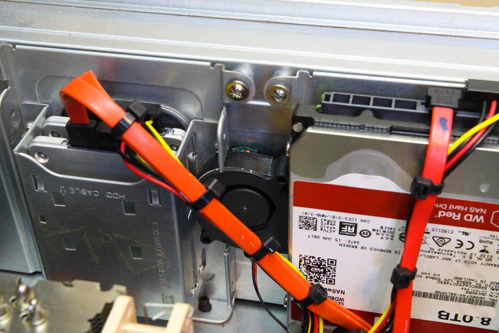
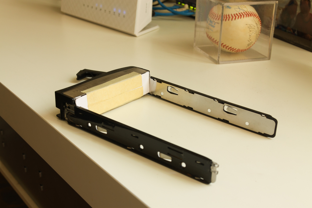
[2018 Update:] I ended up removing this scratch disk and replacing it with a pair of SATA SSDs. [2017 Update:] I wanted an extra drive to host a ZFS pool outside the main volume. This pool would just be a single disk and would be for data that didn't need to be stored with redundancy on the main pool. This drive is mounted to a tray that sits right up against the back of the power supplies on the inside of the chassis and it tended to get much hotter than all the front-mounted drives. My fan control script goes off of maximum drive temperature, so this scratch disk kept the fans running faster than they would otherwise. To help keep this drive cool, I drilled new holes in the drive tray to give a bit of space between the back of the drive and the chassis wall. I also cut a small hole in the side of the drive tray and mounted a little blower fan blowing into the hole so that air would circulating behind the drive. I had to cut away a portion of the SSD mounting tray to accommodate the blower fan. In the end, I'm not sure if the blower fan with its whopping 4 CFM of airflow makes any difference, but it was a pain to get in there so I'm leaving it. In fact, I ended up just modifying the fan script to ignore this scratch disk, but I do keep an eye on its temperature to make sure it's not burning up. A picture of the blower fan is below:
As this was my first server build, I was a little surprised that unlike consumer computer equipment, server equipment doesn’t come with any of the required screws, motherboard standoffs, etc., that I needed to mount everything. Make sure you order some extras or have some on-hand. I ordered a 100-pack of SuperMicro HDD tray screws on Amazon for $6 shipped; I would recommend using these screws over generic ones because if you use screws that don’t sit flush with the HDD sled rails, you’ll have a lot of trouble getting the sled back in the chassis and could even damage the chassis backplane.
As I mentioned above, the CPU cooler I’m using provides enough vertical clearance for the RAM, but I will probably have to remove the cooler to actually get the RAM into the slot if I ever need to add RAM. This isn’t a huge deal as the cooler is really very easy to install. I will note here that the cooler came with 2 different sets of mounting brackets for the LGA2011-v3 narrow ILM system so you can orient the airflow direction either front-to-back or side-to-side (allowing you to rotate the cooler in 90 degree increments). Obviously, for this system, I wanted air flowing in from the HDD side and out the back side, so I had to use the appropriate mounting bracket (or, more accurately, I realized there were two sets of narrow ILM brackets only after I installed the incorrect set on the cooler).
The front panel connector was a little confusing as the non-maskable interrupt (NMI) button header is in the same assembly on the motherboard as all the front panel headers (this header assembly is marked “JF1” on the motherboard and is not very clearly described in the manual). The connectors for all the front panel controls and LEDs are also contained in one single plug with 16 holes and no discernible orientation markings. After studying the diagrams in the motherboard manual, I was able to determine that the NMI button header pins are the 2 pins on this JF1 assembly that are closest to the edge of the motherboard, then (moving inwards) there are 2 blank spots, and then the 16 pins for the rest of the front panel controls and LEDs. The 16 pin front panel connector plugs into these inner 16 pins and should be oriented so the cable exits the 16 pin connector towards the PSU side of the chassis. Basically, if you have the front panel connector plugged into these 16 pins but the power button isn’t working, try flipping the plug around. If you have an NMI button (not included in the stock chassis), it will plug into those last 2 pins closest to the motherboard’s edge. If you don’t have an NMI button, just leave those pins empty.
I also swapped out the rear fans for quieter Noctua 80mm models at this point. The only way to mount them in the chassis is with the hot swap caddies (the chassis isn’t drilled for directly-mounted fans), but the process is pretty straight-forward. The stock fans have very short cables, maybe 1 inch long, because the PWM connectors are mounted onto the side of the caddie so they can mate with the hot-swap plug on the chassis itself when you slide the caddie into its “rail” system. That plug connects to what is essentially a PWM extension cable mounted to the caddie rails which connects the fans to the motherboard’s PWM fan headers. I took out this whole hotswap mechanism because the Noctua fan cables are much longer than the stock fan cables and the Noctua PWM connectors are missing a small notch on the plug that is needed to secure it in the hot swap caddie. It’s tough to describe, but it would be pretty obvious what I mean if you examine the rear fan caddies yourself.
With all the server guts installed and connected, I did some basic cable management and prepared to install my 120mm fan wall. I started by using zip-ties to attach the 3 fans together (obviously ensuring they would all blow in the same direction). The Noctua fans have soft silicone pads in each corner, so vibrations shouldn’t be a big issue if you get the pads lined up right. I put the fan wall in place in the chassis and marked off where the zip tie mounts should be placed with a marker, stuck the mounts on the marks (4 in total on the bottom), and used more zip ties to mount the fan wall in place. With the bottom of the fan wall secured in place, the whole thing is pretty solid, but I added one more zip tie mount to the top of the wall on the PSU side. This sort of wedges the fan wall in place and makes it all feel very secure. Once the fans were secure, I connected them to the 3-to-1 PWM fan splitter, attached that to the FANA header (this is important for the fan control script discussed later), and cleaned up all the cables.
[2019 Update:] The center fan wall and the front fans discussed below are no longer connected to the motherboard. With the modifications I did to the fan control setup, these fans are connected directly to an independent Raspberry Pi system that generates the PWM signals based on commands received from a script on the FreeNAS itself. Power for the fans is provided by a +12V line spliced in from the PSU.
While I’m talking about the HDD fan wall, I’ll also mention here that after running the server for a few days, I noticed some of the drive temperatures were in the low 40s (Celsius), much higher than they should be. The Noctua fans I originally had installed maxed out at 1500 RPMs, but I decided I would be safer with the Noctua iPPC fans that could hit 3000 RPM. I have a fan control script running (more on that below), so they hardly ever need to spin faster than 1500 RPM, but it’s nice to know the cooling is there if I ever need it. In addition to upgrading my original fans, I made a few minor modifications to improve overall cooling efficiency for the whole system:
I used masking tape to cover the ventilation holes on the side of the chassis. These holes are on the hard drive side of the fan wall and are intended to prevent the stock fans from starving, but with lower speed fans they allow air to bypass the hard drives which cuts the total cooling efficiency.
I cut pieces of index cards and used masking tape to block air from flowing through the empty drive bays. The air flow resistance through the empty bays was much lower than it was through the populated bays so most of the air was bypassing the hard drives. You can see a picture of it here. [2017 Update:] These bays are now populated with drives, so the index cards and masking tape came off!
Air was flowing from the CPU side of the HDD fan wall back over the top of the fans rather than coming through the HDD trays, so I cut a long ~3/4” thick strip of wood to block the space between the top of the fans and the chassis lid. I measured the wood strip to be a very tight fit and zip-tied it to the fans to secure it in place. I even cut out little divots where the zip ties cross the top of the wood strip to be extra cautious. You can see this wood strip in the 3rd and 4th pictures in the section above.
[2017 Update:] The fans started to get noisy in the summer when ambient temperatures went up, so I took more drastic measures. I designed a bezel that fits over the front part of the chassis and allows me to mount 3x 140mm fans blowing air into the drive bays from the outside. The bezel is secured in place with zip ties and powered via a PWM extension cable that I ran through one of the side vent holes and along the outside of the chassis. This fan bezel has had a substantial improvement in overall airflow and noise level. More information on it just below.
With these simple modifications in place, effective airflow to the drives increased dramatically and HDD temps dropped by ~10C even with fan speeds under 1500 RPM. You can check relative airflow levels to the hard drive bays by holding a piece of paper up in front of the drive bays and observing the suction force from the incoming air. With a heavy workload, the fans sometimes spin up to 2000 RPM for a minute or two, but overall the system is very quiet. The fan control script I’m running is set to spin up when any drive gets above 36C.
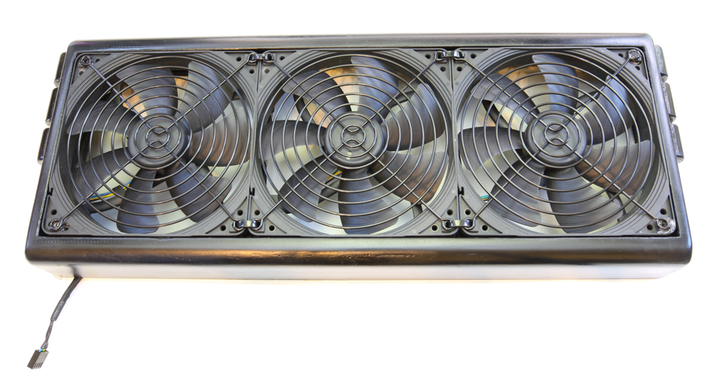
[2017 Update:] I built this machine in the fall, and through the colder winter months, the cooling I had in place was able to keep up with the heat output without making too much noise. When summer rolled around, however, the fans started to get annoyingly loud. I eventually decided to design a fan shroud for the front of the server. It would allow me to mount 3x 140mm fans in front of the drive bays blowing inward. I had the part 3D printed via 3DHubs in PLA (10um layer size) and it turned out pretty nice. There's a link to the 3D model of the bezel below. After a lot of sanding, priming, painting, and some light bondo application, I ended up with piece below:
[2025 Update:] I now have several of these fan shrouds finished (sanded, painted, fans and guards installed) available for sale. I can also 3D print a fresh shroud if you would prefer to finish it yourself. If you're interested, please get in touch: jason@jro.io

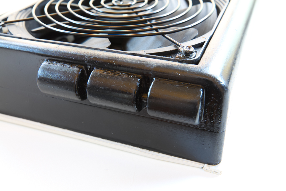
The 20d nail run through these knobs allows for more secure mounting.
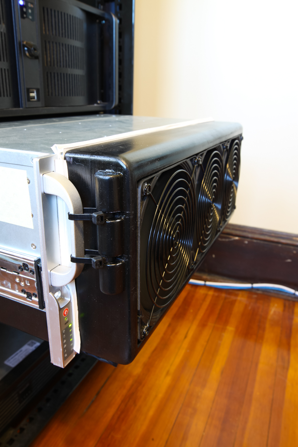
The shroud is zip-tied to the chassis handles. Also note the weather stripping.
The PWM extension cable is run out of one of the side vent holes and along the bottom of the chassis (covered with black tape).
[2017 Update ctd.] The 3D model for the fan bezel can be found on Sketchfab. You should be able to download the STL file on that same page. There are a few things to note about the model for anyone that wants to try something similar:
The assembly is designed to be mounted to the chassis with zip ties that loop between the chassis handles and a 20d nail inserted in the holes on the "knob" things on the sides of the bezel. I cut the heads and the points off of a couple 20d nails (leaving a straight metal rod), put them in the holes in the knobs and glued them in place with CA model glue. This lets you run the zip ties through a metal piece and secure everything far more tightly than you would be able to with plastic-only.
The fans are powered via a PWM extension cable that I threaded through a vent hole in the side of the chassis and ran along the bottom. I had to disconnect the plug on one end of the cable, but this is pretty easy to do with a small screwdriver. I used a 3-way PWM splitter to connect all the fans to this single extension cable.
The fans are obviously oriented to blow inward, so the "back" or suction side of the fans is facing out towards the room. This side of the fan doesn't have any sort of guard built into it, so I used some wire fan guards to ensure fingers and dog noses don't get nipped.
The "knobs" on the inside of the part are designed to let you zip tie fans in place. The 4 knobs in the corners have a small hole for the zip tie to be threaded through, but these came out unusably small in my print. I ended up securing the fans in place using only the 4 inner knobs and glued the fan guards down in the 4 corners. If you would prefer to use secure the fans and fan guards with screws, you may need to resize the screw holes as they're slightly larger than standard fan holes.
I designed 3 cutouts on the inside bottom of the bezel for tape-down zip tie mounts. I ended up not using these because the zip tie mounts prevented the bottom of the bezel from contacting the chassis; the zip tie mounts hit the drive trays, which protrude from the front of the server quite a bit.
There is a small cutout in the bottom left corner for the PWM cable to exit the bezel. If you run a PWM extension cable down the right side of your chassis, you'll want to relocate this cutout.
If you have your server installed in a rack with a front door, it's worth checking that the bezel won't protrude so far forward that it blocks the door from shutting. I ended up with maybe 5mm of clearance with the weather stripping installed.
The bezel didn't make a very tight seal with the chassis, so a lot of air was escaping around the edges. I got some weather stripping tape from the hardware store, applied a strip around the bezel and another around the chassis and it fixed this problem nicely. It also provided a bit more clearance for the cable bundle on the inside of the bezel which was jammed up against the front of the drive trays before.
[2017 Update ctd.] The fan bezel has had a significant impact on overall cooling performance and noise level. Without the bezel, the internal 120mm fans would need to run at 2000+ RPM almost constantly during the summer months. Now that the bezel is installed, I can keep the fans at 1200-1300 RPM and all the drives are just as cool as before.
[2017 Update ctd.] I made a short video that covers the various changes I made to my chassis' cooling system and demonstrates the noise level at various fan speeds:
The last step in the system build was to get all the hard drives loaded into their sleds and slide them into the chassis. If you aren’t populating all 24 bays in the chassis, be sure to note which mini-SAS ports connect to which bays; this is labeled on the rear of the backplane and in the backplane manual.
[2017 Update:] With everything built, I could load the server and the UPS into the rack cabinet. The inner rails snapped right into place on the sides of the chassis and the outter rails slotted directly into the square holes on the rack posts. I originally had the outer rails installed a third of a rack unit too low, so I had to move them up a slot. If you're unsure of which set of holes to use for the outter rails so your machine lines up with the marked rack units, check the photos above of my machine in the rack. The UPS is just sitting on the floor of the rack cabinet (which solid steel and seems extremely study) and occupies the lowest 2U.
[Original text with details on building the LackRack:] With everything built, I could load the server and the UPS into the LackRack. The UPS went on the floor and the server went on the lower shelf. I have all my networking gear on the top shelf along with some other knick-knacks. Assembly of the LackRack itself was pretty easy, but there were a few minor things worth noting. I picked up some basic metal corner braces from a hardware store for reinforcement of the lower shelf; they’re around 3” long and 3/4” wide and seem to work pretty well. I mounted the braces to the legs of the table and the underside of the lower shelf with basic wood screws. The lower shelf is only ~1/3” thick, so I got very stubby screws for that side of the brace. When measuring how low or high to install the lower shelf, I forgot to make sure leave enough room for the server to sit in the space and had to re-do part of the installation at a lower height. For a 4U server (like the one I’ve got), you’ll need a smidge over 7”, so the shelf has to go an inch or two lower than the IKEA instructions would have you mount it. The legs of the table (into which I mounted the braces) are very light weight; it feels like they’re totally hollow except for a small solid area around the middle where you’re supposed to mount the tiny IKEA-provided braces that come with the table. Don’t over-tighten the screws you put into the legs even a little bit, otherwise it will completely shred out the wood and won’t be very secure. In fact, while I was installing one of the braces, I leaned on my screw gun a bit too hard and before I even started to turn the screw, it broke through the outer “wall” of the leg and just went chonk and fell down into place. Not a confidence-inspiring event while building the “rack” that will soon house my ~$5,000 server... Regardless, with all the corner braces installed, the two shorter ends of the shelf seem pretty sturdy. However, the shelf is so thin that it would have started to sag (and could have possibly broken) with any weight in the middle. With a file server, most of the weight is in the front due to the drives, but I thought it was still a good idea to brace the middle of the shelf from the underside. I cut a short piece of 2x4 that I could use to prop up the middle of the lower shelf from underneath.
With everything installed and mounted, I was finally ready to power on the system for the first time and move on to the installation and configuration process!
Flashing the M1015 HBA Cards & Installing FreeNAS
[2019 Update:] The two new LSI HBAs I bought to replace the M1015's do not require any crossflashing or reflashing (unless the firmware is out of date). The process below is for the IBM cards which are just re-branded LSI 9211-8is. The crossflashing operation with the MEGAREC utility lets you erase the IBM firmware and put LSI's firmware back on them. Again, with the newer LSI cards I got, this isn't necessary because they're already running LSI's IT firmware out of the box.
I was pretty lucky and my server POST’d on the first try. Before actually installing an OS, I needed to flash the M1015 cards with the IT mode firmware. This article has instructions on that process. The download linked in that article goes down quite a bit, so I’ve rehosted the necessary firmware files here [.zip file]. This file contains 3 DOS applications (sas2flsh.exe, megarec.exe, and dos4gw.exe), the IT firmware image (2118it.bin), the BIOS image file (mptsas2.rom), and an empty file for backing up stock card firmware (sbrempty.bin). If you're flashing more than one card, you will want to copy this file so you have one per card. The sas2flsh and megarec applications are used below to back up, erase, and reflash the cards. The dos4gw application allows these applications to address more memory space than they would be able to otherwise, but you won't need to run it directly.
I used Rufus to create a bootable FreeDOS USB drive and copied in the files from the above .ZIP archive. Before performing the rest of the process, it is a good idea to visit the controller manufacturer’s website to make sure you’re using the most recent firmware image and BIOS. They change the layout and URL of the official Broadcom website that hosts the firmware, so just search Google for “SAS 9211-8i firmware”, find the downloads section, and open the firmware sub-section. The versions are marked by “phase” numbers; the firmware/BIOS version I included in the above ZIP file is from phase 20 or “P20” as it’s listed on the site. If a more recent version is available, download the MSDOS and Windows ZIP file, find the BIOS image (called mptsas2.rom) and the IT firmware (called 2118it.bin; you do not want the IR firmware called 2118ir.bin) and copy them both onto your bootable USB drive overwriting the files I provided.
With the SAS addresses I wrote down during the build process on hand, I booted from my USB drive into the FreeDOS shell and executed the following from the DOS terminal:
megarec -adpList
MegaREC is a utility provided by LSI that I'll use to back up each card's original firmware and then wipe them. The above command lists all the adapters it finds; make sure all your cards are listed in its output. When I originally flashed my cards, I had two installed, so I run each command once per card with the adapter number after the first flag. I made two copies of the sbrempty.bin file, called sbrempty0.bin and sbrempty1.bin; make sure to adjust your -writesbr commands accordingly. If you only have one card, you can omit the adapter number. Run the following commands to back up and wipe each of the cards:
megarec -writesbr 0 sbrempty0.bin
megarec -writesbr 1 sbrempty1.bin
megarec -cleanflash 0
megarec -cleanflash 1
(Reboot back to USB drive.)
Once I backed up and wiped all the cards, I rebooted the server. When it came online (again in FreeDOS), I could flash the cards with the IT mode firmware using the following commands:
sas2flsh -o -f 2118it.bin -c 0
sas2flsh -o -f 2118it.bin -c 1
sas2flsh -o -sasadd 500605bXXXXXXXXX -c 0
sas2flsh -o -sasadd 500605bXXXXXXXXX -c 1
(Shut down and remove USB drive.)
There are a couple of things to note here. As above, the -c 0 and -c 1 at the end of these commands specify the controller number. If you’re also following the guide I linked above, you may notice that I’ve left out the flag to flash a BIOS (-b mptsas2.rom) in the first set of commands. This is because I don’t need a BIOS on these cards for my purposes; you will need the BIOS if you want to boot from any of the drives attached to the controller (but don’t do that... Either use USB drives or connect your SSDs directly to the motherboard SATA ports). I’ve included the latest BIOS file in the zip just in case someone needs it; just add -b mptsas2.rom to the end of the first (set of) command(s), but again, you really shouldn’t need it. The last thing to note is the SAS addresses in the second set of commands. The XXXXXXXXX part should be replaced with last part of the SAS address of that controller (without the dashes). Make sure the address matches up with the correct card; you can run sas2flsh -listall to check the PCI addresses if you aren’t sure which controller number maps to which physical card. The -listall command requires firmware to be flash to the card or else it will throw an error and prompt for the firmware filename, so run it after the -f commands. After all the cards were flashed, I powered down the server, removed the USB drive, and prepared to install FreeNAS.
I downloaded the latest FreeNAS 9.10 ISO from here, used Rufus again to make a bootable USB drive with it, and started the install process by booting off the USB stick. The FreeNAS installation process in very easy. When selecting the boot volume, I checked off both my SSDs and FreeNAS handled the mirroring automatically. After the installation finished, I rebooted the system from the SSDs and the FreeNAS web UI came online a few minutes later.
Initial FreeNAS Configuration
The very first thing I did in the FreeNAS configuration is change the root password and enable SSH. I also created a group and user for myself (leaving the home directory blank to start with) so I didn’t have to do everything as root. If you’re having trouble getting in via SSH, make sure the SSH service is actually enabled; in the web UI, go to Services > Control Services and click the SSH slider to turn the service on.
With SSH access set up, I connected to a terminal session with my new FreeNAS machine and followed this guide on the FreeNAS forums for most of my initial setup, with a few minor modifications. The text in this section is largely based off that guide. My first step is to determine the device names for all the installed disks. You can do this by running:
camcontrol devlist
After determining the device names, I did a short SMART test on each of my drives using:
smartctl -t short /dev/da<#>
Where da<#> is the device name from the camcontrol devlist output. The test only takes a couple minutes and you can view the results (or the ongoing test progress) using:
smartctl -a /dev/da<#>
After checking that all the SMART tests passed, I created my primary volume. My process was a little non-standard because I moved my 4TB drives into the server after I transferred the data off them, so I’ll go through my process first and discuss the standard process afterwards. However, before diving into that, I want to review how ZFS allocates disk space and how it can be tuned to minimize storage overhead (by as much as 10 percent!). This next section gets pretty technical and if you aren’t interested in it, you can skip it for now.
Calculating & Minimizing ZFS Allocation Overhead
Calculating the disk allocation overhead requires some math and an understanding of how ZFS stripes data across your disks when storing files. Before we get into the math, let’s take a look at how ZFS stores data by discussing two examples:
Storing a very small file, and
Storing a large(r) file.
We’ll start out with the small file. Hard disks themselves have a minimum storage unit called a “sector”. Because a sector is the smallest unit of data a hard disk can write in a single operation, any data written to a disk that is smaller than the sector size will still take up the full sector. It's still possible for a drive to perform a write that's smaller than its sector size (for instance, changing a single byte in an already-written sector), but it needs to first read the sector, modify the relevant part of the sector's contents, and then re-write the modified data. Obviously this sequence of three operations will be a lot slower than simply writing a full sector’s worth of data. This read-write-modify cycle is called "write amplification".
On older hard drives (pre ~2010), the user data portion of a sector (the part we care about) is typically 512 bytes wide. Newer drives (post ~2011) use 4096-byte sectors (4KiB, or simply 4K). Each hard disk sector also has some space for header information, error-correcting code (ECC), etc., so the total sector size is actually 577 bytes on older drives and 4211 bytes on newer drives, but we only care about the portion in each sector set aside for user data; when I refer to a “sector”, I’m referring only to the user data portion of that sector.
Because the hard disk sector size represents the smallest possible unit of storage on that disk, it is obviously a very important property for ZFS to keep track of. ZFS keeps track of disk sector sizes through the “alignment shift” or ashift parameter. The ashift parameter is calculated as the base 2 logarithm of a hard disk’s sector size and is set per virtual device (“vdev”). ZFS will attempt to automatically detect the sector size of its drives when you create a vdev; you should always double-check that the ashift value is set accurately on your vdev as some hard disks do not properly report their sector size. For a vdev made up of older disks with 512-byte sectors, the ashift value for that vdev will be 9 (\(2^9 = 512\)). For a vdev made up of newer disks with 4096-byte sectors, the ashift value for that vdev will be 12 (\(2^{12} = 4096\)). Obviously, mixing disks with 512-byte sectors and disks with 4096-byte sectors in a single vdev can cause issues and isn’t recommended; if you set ashift = 9 in a vdev with 4K drives, performance will be greatly degraded as every write will require the read-modify-write operation sequence I mentioned above in order to complete. It follows then that 2^ashift then represents the smallest possible I/O operation that ZFS can make on a given vdev (or at least before we account for parity data added on by RAID-Z).
Let’s quickly review how data is stored on a “striped” RAID configuration (i.e., RAID 5, RAID 6, RAID-Z, RAID-Z2, and RAID-Z3) before going any further. On these RAID configurations, the data stored on the array will be spread across all the disks that make up that array; this is called “striping” because it writes the data in “stripes” across all the disks in the array. You can visualize this with a 2-dimensional array: the columns of the array are the individual disks and the rows are the sectors on those disks (a full row of sectors would then be called a “stripe”).
When you write data to a RAID 5 or RAID 6 system, the RAID controller (be it hardware or software) will write that data across the stripes in the array, using one sector per disk (or column). Obviously, when it hits the end of a row in the array, it will loop back around to the first column of the next row and continue writing the data. RAID 5 and RAID 6 systems can only handle full-stripe writes and will always have 1 parity sector per stripe for RAID 5 and 2 parity sectors per stripe for RAID 6. The parity data is not stored on the same disk(s) in every row otherwise there would be a lot of contention to access that disk. Instead, the parity sectors are staggered, typically in a sort of barber pole fashion, so that when you look at the whole array, each disk has roughly the same number of parity sectors as all the others. Again, this ensures that in the event of a bunch of small writes that should only involve writing to two or three disks, one disk is bogged down handling all the parity data for every one of those writes. Because RAID 5 and 6 can only handle full-stripe writes, if it's told to write data that is smaller than a single stripe (minus the parity sectors), it needs to read the data in that stripe, modify the relevant sectors, recalculate the parity sector(s), and rewrite all sectors in the stripe. Very similar to the write amplification example above, this long sequence of events to handle a single small write ends up hobbling performance.
RAID-Z can handle partial-stripe writes far more gracefully. It simply makes sure that for every block of data written, there are \(p\) parity sectors per stripe of data, where \(p\) is the parity level (1 for Z1, 2 for Z2, and 3 for Z3). Because ZFS can handle partial-stripe writes, ZFS doesn't pay special attention to making sure parity sectors are "barber poled" as in RAID 5 and 6. Lots of small write operations that would cause contention for a single parity disk as above would just get their own pairty blocks in their own partial-stripe write. It should be noted that ZFS stripes the data down the array rather than across it, so if the write data will occupy more than a single stripe, the second sector of the data will be written directly under the first sector (on the next sector in the same disk) rather than directly to the right of it (on a sector on the next disk). It still wraps the data around to the next disk in a similar fashion to RAID 5 and 6, it just does it in a different direction. If the write data fits in a single stripe, it stripes the data across the array in an almost identical manner to RAID 5 and 6. ZFS's vertical RAID-Z stripe orientation doesn't really impact anything we'll discuss below, but it is something to be aware of.
Getting back on track, we were discussing the smallest possible writes one can make to a ZFS array. Small writes will obviously be used for small file sizes (on the order of a couple KiB). The smallest possible write ZFS can make to an array is:
$$ n_{min} = 1+p $$
As above, p is the parity level (1 for RAID-Z1, 2 for RAID–Z2, and 3 for RAID-Z3) and the 1 represents the sector for the data itself. So \(n_{min}\) for various RAID-Z configurations will be as follows:
$$ \text{RAID-Z1: } n_{min} = 2 $$
$$ \text{RAID-Z2: } n_{min} = 3 $$
$$ \text{RAID-Z3: } n_{min} = 4 $$
When ZFS writes to an array, it makes sure the total number of sectors it writes is a multiple of this \(n_{min}\) value defined above. ZFS does this to avoid situations where data gets deleted and it ends up with a space on the disk that’s too small to be used (for example, a 2-sector wide space can’t be used by RAID-Z2 because there’s not enough room for even a single data sector and the necessary two parity sectors). Any sectors not filled by user data or parity information are known as “padding”; the data, parity information, and padding make up the full ZFS block. Padding in ZFS blocks is one of the forms of allocation overhead we’re going to look at more closely. Study the table below for a better idea of how block padding can cause storage efficiency loss. Note that this table assumes everything is written to a single stripe; we’ll look at how data is striped and how striping can cause additional overhead in the next section.
| Data, Parity, and Padding Sectors with Efficiency (Note: Assumes Single Stripe) | ||||||||||||
|---|---|---|---|---|---|---|---|---|---|---|---|---|
| Data Sectors |
Parity Sectors | Padding Sectors | Total Sectors (Block Size) |
Efficiency (Data/Total) |
||||||||
| Z1 | Z2 | Z3 | Z1 | Z2 | Z3 | Z1 | Z2 | Z3 | Z1 | Z2 | Z3 | |
| 1 | 1 | 2 | 3 | 0 | 0 | 0 | 2 | 3 | 4 | 50.0% | 33.3% | 25.0% |
| 2 | 1 | 2 | 3 | 1 | 2 | 3 | 4 | 6 | 8 | 50.0% | 33.3% | 25.0% |
| 3 | 1 | 2 | 3 | 0 | 1 | 2 | 4 | 6 | 8 | 75.0% | 50.0% | 37.5% |
| 4 | 1 | 2 | 3 | 1 | 0 | 1 | 6 | 6 | 8 | 66.7% | 66.7% | 50.0% |
| 5 | 1 | 2 | 3 | 0 | 2 | 0 | 6 | 9 | 8 | 83.3% | 55.6% | 62.5% |
| 6 | 1 | 2 | 3 | 1 | 1 | 3 | 8 | 9 | 12 | 75.0% | 66.7% | 50.0% |
| 7 | 1 | 2 | 3 | 0 | 0 | 2 | 8 | 9 | 12 | 87.5% | 77.8% | 58.3% |
| 8 | 1 | 2 | 3 | 1 | 2 | 1 | 10 | 12 | 12 | 80.0% | 66.7% | 66.7% |
| 9 | 1 | 2 | 3 | 0 | 1 | 0 | 10 | 12 | 12 | 90.0% | 75.0% | 75.0% |
| 10 | 1 | 2 | 3 | 1 | 0 | 3 | 12 | 12 | 16 | 83.3% | 83.3% | 62.5% |
| 11 | 1 | 2 | 3 | 0 | 2 | 2 | 12 | 15 | 16 | 91.7% | 73.3% | 68.8% |
| 12 | 1 | 2 | 3 | 1 | 1 | 1 | 14 | 15 | 16 | 85.7% | 80.0% | 75.0% |
| 13 | 1 | 2 | 3 | 0 | 0 | 0 | 14 | 15 | 16 | 92.9% | 86.7% | 81.3% |
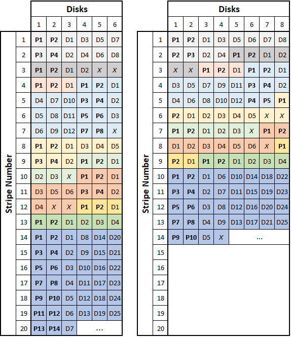
If the data you’re writing fits in a single stripe, ZFS will allocate the block based on the above table, again making sure that the block size is a factor of \(n_{min}\). When the data you’re writing doesn’t fit in a single stripe, ZFS simply stripes the data across all the disks in the array (again, in the vertical orientation discussed above) making sure that there is an appropriate quantity of parity sectors per stripe. It will still make sure the size of the block (which is now spread across multiple stripes and contains multiple sets of parity sectors) is a factor of \(n_{min}\) to avoid the situation outlined above. When considering how ZFS stripes its data, remember that RAID-Z can handle partial stripe writes. This means that RAID-Z parity information is associated with each block rather than with each stripe; thus it is possible to have multiple sets of parity sectors on a given disk stripe if there are multiple blocks per stripe. The below figures show (roughly) how ZFS might store several data blocks of varying sizes on a 6-wide and an 8-wide RAID-Z2 array. Data sectors are preceded by a "D", parity sectors by a "P", and padding sectors are indicated by an "X". Each set of colored squares represents a different ZFS block.
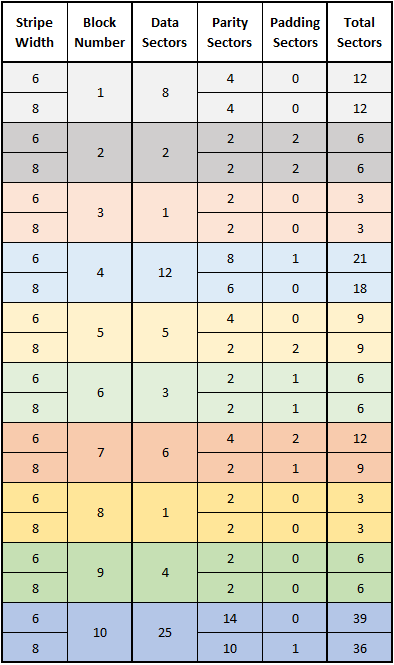
If we define \(w\) as the stripe width (or the number of disks in the array), we can see that ZFS will make sure there are \(p\) parity sectors for every set of \(1\) to \(w-p\) data sectors so a disk failure doesn’t compromise the stripe. In other words, if there are between \(1\) and \(w-p\) user data sectors, the ZFS block will have \(p\) total parity sectors. If there are between \((w-p)+1\) and \(2(w-p)\) user data sectors, the block will have \(2p\) total parity sectors. This point can be tough to conceptualize, but if you study all the examples in the above figure, you should see what I mean by this. It is also interesting to compare the number of total sectors that are required to store a given number of data sectors for the 6-wide and 8-wide RAID-Z2 examples. The table below shows this comparison.
Note first that all the numbers in the “Total Sectors” column are divisible by
$$ n_{min} = 1+p = 1+2 = 3 $$
This is due to the “padding” sectors allocated at the end of the blocks so their lengths are divisible by \(n_{min}\). Because of this, the sequence in which these blocks are stored is irrelevant when we determine how many total sectors will be required to store that data. Comparing the values in the two “Total” columns (particularly for the larger data blocks) hint at the next form of overhead we will cover.
To review, ZFS dynamically sizes data blocks based on the amount of user data and parity in that block. The smallest block size is
$$ n_{min} = 1+p $$
Where \(p\) is the parity level. The blocks can grow in increments of \(n_{min}\). We also defined \(w\) as the stripe width. Next, we’ll look at how larger writes are handled (for files of a couple MiB and larger).
The maximum size of a ZFS data block size is controlled by a user-definable parameter called recordsize. Its value represents the maximum amount of data (before parity and padding) that a file system block can contain. The default value for the recordsize parameter in a FreeNAS is 128KiB, but you can set the value to any power of 2 between 512b and 1MiB. The recordsize parameter can be set per ZFS dataset and even modified after the dataset is created (but will only affect data written after the parameter is changed). You may realize at this point that blocks of length recordsize might not always contain a total number of sectors that is divisible by \(n_{min}\)... We’ll get to this in just a bit.
We now have all four parameters we need to consider when calculating the allocation overhead of a ZFS array: A ZFS block’s recordsize, the vdev’s parity level (\(p\)), the vdev’s stripe width (\(w\)), and disks’ sector size (ashift). The allocation overhead will be calculated as a percentage of the total volume size so it is independent of individual disk size. To help us understand how all of these factors fit together, I will focus on 4 different examples. We will go through the math to calculate allocation overhead (defined below) for each example, then look at them all visually. The four examples are as follows:
| Ex. Num | Parity Level | Stripe Width | recordsize | sector size (ashift) |
|---|---|---|---|---|
| 1 | 2 (RAID-Z2) | 6 | 128KiB |
4KiB (12) |
| 2 | 2 (RAID-Z2) | 8 | 128KiB |
4KiB (12) |
| 3 | 2 (RAID-Z2) | 6 | 1MiB |
4KiB (12) |
| 4 | 2 (RAID-Z2) | 8 | 1MiB |
4KiB (12) |
As we will see later on, the parity level, stripe width, and ashift values are typically held constant while the recordsize value can be tuned to suit the application and maximize the storage efficiency by minimizing allocation overhead. If the parity level and stripe width are not held constant, decreasing parity level and/or increasing stripe width will always increase overall storage efficiency (more on this below). The ashift parameter should not be adjusted unless ZFS incorrectly computed its value.
For the first example, we’ll look at a 6-wide RAID-Z2 array with 4KiB sectors and a recordsize of 128KiB. 128KiB of data represents 128KiB/4KiB = 32 total sectors worth of user data. Since we’re using RAID-Z2, we need 2 parity sectors per stripe, leaving 6-2 = 4 sectors per stripe for user data. 32 total sectors divided by 4 user data sectors per stripe gives us 8 total stripes. 8 stripes * 2 parity sectors per stripe gives us 16 total parity sectors. 16 parity sectors + 32 data sectors give us 48 total sectors, which is divisible by 3, so no padding sectors are needed. In this example, you will notice that all the numbers divided into each other nicely. Unfortunately, this is not always the case in every configuration.
In our second example, we’ll now look at an 8-wide RAID-Z2 array. The array will still use 4KiB sector disks and will still have a recordsize of 128KiB. We will still need to store 128KiB/4KiB = 32 total sectors worth of user data, but now we have 8-2 = 6 sectors per stripe for user data. 32 data sectors/6 sectors per stripe gives us 5.333 total stripes. As we saw in the previous section, we can’t have .333 stripes worth of parity data. ZFS creates 5 full stripes (which cover 30 sectors worth of user data) and 1 partial stripe for the last 2 sectors of user data, but all 6 stripes (5 full stripes and 1 partial stripe) need full parity data to maintain data resiliency. This “extra” parity data for the partial stripe is our second source of ZFS allocation overhead. So we have 32 data sectors and 6*2 = 12 parity sectors giving us a total of 44 sectors. 44 is not divisible by 3, so we need one padding sector at the end of the block, bringing our total to 45 sectors for the data block.
Before continuing to the final two examples, it would be worthwhile to generalize this and combine it with what we discussed in the previous section. We have the two sources of allocation overhead defined, which are:
Padding sectors added to the end of a data block so the total number of sectors in that block is a multiple of \(n_{min}\)
Parity sector(s) on partial stripes
We can say that the size of a given ZFS data block (in terms of the number of disk sectors) will be dynamically allocated somewhere between \(n_{min}\) and \(n_{max}\) and will always be sized in multiples of \(n_{min}\) (where \(n_{min}\) and \(n_{max}\) are defined below):
$$ \bf{n_{min}} = 1 + p $$
$$ \bf{n_{max}} = n_{data} + n_{parity} + n_{padding} $$
$$ n_{data} = \frac{recordsize}{2^{ashift}} $$
$$ n_{parity} = ceiling\left(\frac{n_{data}}{w-p}\right) * p $$
$$ n_{padding} = ceiling\left(\frac{n_{data} + n_{parity}}{n_{min}}\right) * n_{min} - (n_{data} + n_{parity}) $$
$$ p = \text{vdev parity level} $$
$$ w = \text{vdev stripe width} $$
Once a file grows larger than the dataset’s recordsize value, it will be stored in multiple blocks, each with a length of \(n_{max}\).
The value of \(n_{max}\) will be our primary focus when discussing allocation efficiency and how to maximize the amount of data you can fit on your array. If your application is anything like mine, the vast majority of your data is made up of files larger than 1MiB. By defining one additional value, we can calculate the allocation overhead percentage:
$$ n_{theoretical} = w * \frac{n_{data}}{w-p} $$
$$ overhead = \left(\frac{n_{max}}{n_{theoretical}} -1 \right) * 100\% $$
In the first example above, we calculated \(n_{max}\) as 48 sectors. For the same example,
$$ n_{theoretical}(Ex. 1) = 6 * \frac{32}{6-2} = 48 $$
$$ overhead(Ex. 1) = \left(\frac{48}{48}-1\right) * 100\% = 0\% $$
As we saw while working through the example, everything divided nicely, so we have no allocation overhead with this configuration.
In the second example, we calculated \(n_{max}\) as 45 sectors. From this, we can calculate the allocation overhead:
$$ n_{theoretical}(Ex. 2) = 8 * \frac{32}{8-2} = 42.6667 $$
$$ overhead(Ex. 2) = \left(\frac{45}{42.6667}-1\right) * 100\% = 5.469\% $$
Data written to the array in example 2 will take up ~5.5% more usable disk space than the same data written to the array in example one. Obviously, an overhead of this amount is undesirable in any system.
You may notice that in example one, it took 48 total sectors to store 128KiB of data while in example two it only took only 45 total sectors to store the same 128KiB. This is because the overhead values calculated above do not account for the space consumed by parity data (except parity data written on partial stripes). As mentioned above, decreasing parity level and/or increasing stripe width will always increase overall storage efficiency, which is exactly what we are seeing here. For our purposes, we are looking at maximizing efficiency by decreasing overhead from data block padding and from parity data on partial stripes. If you wanted to factor parity size of your configuration and allocation overhead into an overall efficiency value, you could use the following:
$$ efficiency = \frac{n_{data}}{n_{max}} * 100\% $$
For our two examples:
$$ efficiency(Ex. 1) = \frac{32}{48} * 100\% = 66.67\% $$
$$ efficiency(Ex. 2) = \frac{32}{45} * 100\% = 71.11\% $$
In this comparison, example 2 stores its data more efficiently overall despite the ~5.5% allocation overhead calculated above. Our next steps will show how we can reduce this overhead value (thus increasing the overall efficiency) by adjusting the recordsize value.
Example three is a revisit of the first example (a 6-wide RAID-Z2 array with 4KiB sectors), but this time we will use a recordsize of 1MiB. 1MiB of data represents 1MiB/4KiB = 256 total sectors for user data. Since we’re still using RAID-Z2, we need 2 parity sectors per stripe, leaving 4 sectors per stripe for user data. 256 total sectors divided by 4 sectors per stripe gives us 64 stripes. 64 stripes * 2 parity sectors per stripe give us 128 total parity sectors. 128 parity sectors + 256 sectors give us 384 total sectors, which is divisible by 3, so no padding is needed. As before, everything divides nicely, so changing the recordsize value didn’t change the allocation overhead (which is still 0%) or the overall storage efficiency (still 66.67%):
$$ n_{theoretical}(Ex. 3) = 6 * \frac{256}{6-2} = 384 $$
$$ overhead(Ex. 3) = \left(\frac{384}{384}-1\right) * 100\% = 0\% $$
$$ efficiency(Ex. 3) = \frac{256}{384} * 100\% = 66.67\% $$
Example four will look at the 8-wide RAID-Z2 setup in example 2, but with a recordsize of 1MiB. Again, 1MiB of data represents 1MiB/4KiB = 256 total sectors for user data. We have 6 sectors per stripe for user data, so 256 total sectors divided by 6 sectors per stripe gives us 42.667 sectors. We end up with 42 full stripes and one partial stripe (but as before, all 43 stripes get full parity information). So we have 256 sectors and 43*2 = 86 parity sectors giving us a total of 342 sectors. 342 is divisible by 3, so no padding sectors are required. The only allocation overhead we have is from the partial stripe parity data. Calculating the overhead, we find that:
$$ n_{theoretical}(Ex. 4) = 8 * \frac{256}{8-2} = 341.33 $$
$$ overhead(Ex. 4) = \left(\frac{342}{341.33}-1\right) * 100\% = 0.196\% $$
$$ efficiency(Ex. 4) = \frac{256}{342} * 100\% = 74.85\% $$
Compare that to the results from Example two:
$$ n_{theoretical}(Ex. 2) = 8 * \frac{32}{8-2} = 42.6667 $$
$$ overhead(Ex. 2) = \left(\frac{45}{42.6667}-1\right) * 100\% = 5.469\% $$
$$ efficiency(Ex. 2) = \frac{32}{45} * 100\% = 71.11\% $$
You’ll recall that the only difference between the configuration in examples two and four are the recordsize value. From these results, it is obvious that changing the recordsize from 128KiB to 1MiB in the 8-wide configuration reduced the allocation overhead which in turn increased the overall storage efficiency of the configuration. You may wonder how such a substantial improvement was achieved when the only difference in overhead factors was the one padding sector in the 128KiB configuration (indeed, both configurations required extra parity data for a partial data stripe). It’s important to remember how much data we are storing per block in each configuration as the overhead is “added” to each block; the first configuration required 3 overhead sectors per 128KiB of data stored, while the second configuration required 2 overhead sectors per 1MiB of data stored. The 3 overhead sectors per block in the 128KiB configuration get compounded very quickly when large amounts of data are written. It’s easy to see this effect visually by looking at the diagrams below. Overhead from padding sectors are highlighted in orange and overhead from partial stripe parity data are highlighted in red. The thick black lines separate the data blocks.
Examples One and Two:
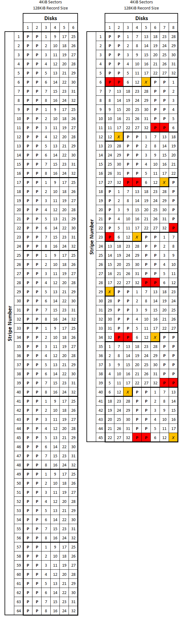
Examples Three and Four:
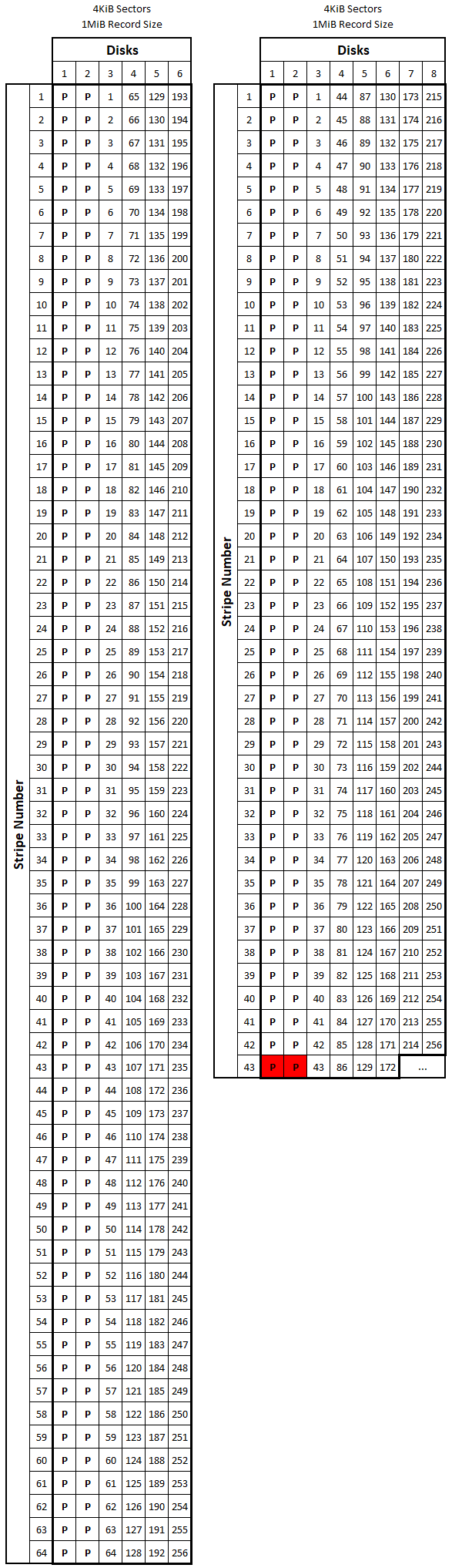
Notice in these diagrams how changing the recordsize on the 6-wide array doesn’t impact allocation overhead; this is because the ZFS configuration aligns with the so-called \(2^n+p\) rule (which states that you should configure your dataset so its stripe width \(w\) is \(2^n+p\) for small-ish values of \(n\)). ZFS datasets that conform to this rule will always line up nicely with the default 128KiB recordsize and have an allocation overhead of 0%. If you’re not interested in fiddling with your dataset’s recordsize value, consider sticking with a configuration that conforms to this rule.
Examining how changing the recordsize value on the 8-wide array impacts the allocation overhead is worth a closer look. The figure below shows examples two and four side-by-side. In example two, notice how the overhead compounds much quicker for a given amount of user data than in example four. Also notice how many total stripes are required to store the given amount of user data in each configuration.
Examples Two and Four:
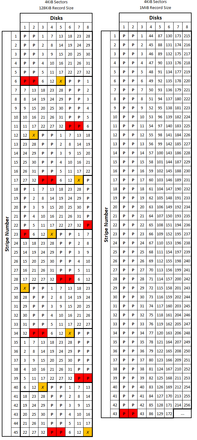
There are a couple final points I want to make on recordsize tuning before moving on. Determining the amount of data written to a disk by ZFS from a file size isn’t always easy because ZFS commonly employs data compression before making those writes. For example, if you’re hosting a database with 8KiB logical blocks, ZFS will likely be able to compress that 8KiB before it is written to disk. There are disadvantages to increasing recordsize to 1MiB in some applications that deal with only very small files (like databases). For my purposes of storing a lot of big files, setting recordsize to 1MiB is a no-brainer. In terms of tuning stripe width and parity level to optimize performance for your application, the articles linked below provide some excellent information.
Much of the above section is based on a calculation spreadsheet (/u/SirMaster on reddit). I also want to thank to Timo Schrappe (twitter @trytuna) for catching a mistake in the above formula for \(n_{padding}\) as well as some typos! If you’re interested in getting an even deeper understanding of the ZFS inner mechanics, I would encourage you to read the following three articles (all of which were tremendously helpful in writing this section):
ZFS RAIDZ stripe width on Delphix; discusses changing vdev parameters to optimize performance for a given application. This article also inspired the ZFS data block write diagrams in this section.
ZFS Record Size on Joyent; discusses the
recordsizeparameter and how it controls ZFS data block size (specifically, the maximum data block size).Tuning ZFS recordsize on the Oracle blog; discusses tuning the
recordsizeparameter based on I/O size.
Here are links to more general (but still very helpful) guides on tuning ZFS parameters:
Open ZFS Performance tuning guide on The Open ZFS wiki; goes into much more depth on several concepts I covered.
ZFS Tuning Guide on the FreeBSD wiki page; similar to the above link.
ZFS Evil Tuning Guide originally on SolarisInternals; like the above tuning guides but evil... So evil in fact that this link and the one above it have been down recently. [2017 Update:] Added mirrors for this link and the one above.
If you're generally interested in the technical analysis of data systems, you may also enjoy reading through my R2-C2 page, which looks at maximizing the reliability of a RAID system from a purely statistical perspective.
Setting Up the Storage Volumes
[2018 Update:] I wrote a couple of blog posts for iXsystems that examine the mechanics of ZFS pool performance in various layouts. If you're unsure which pool layout would be ideal for your use case, you should check them out. Part 1 can be found here, and part 2 can be found here.
When I first set up my server, I didn’t fully understand recordsize tuning, so I created my main storage dataset with a recordsize of 128KiB (the default value). After doing more research, I realized my mistake and created a second dataset with recordsize set to 1MiB. I set up a second SMB share with this dataset and copied all my data from the 128KiB-based dataset to the 1MiB-based dataset; once all the data was moved over, I wiped the first dataset. The reduction in allocation overhead manifests itself on the share by a reduction in the reported “size on disk” value in Windows (where I have my share mounted). The reduction I saw when copying the same data from the 128KiB dataset to the 1MiB dataset was in line with the ~5% overhead reduction demonstrated above.
The proper way to set everything up would have been to first create a volume (close out of the wizard that pops up when you initially log into FreeNAS for the first time) with the volume manager. Volumes are traditionally named tank, but you can call yours whatever you want (the rest of this guide will assume you’ve named it tank). Make sure you have the volume layout correct in the volume manager before hitting “Ok”, otherwise you’ll have to destroy the volume and re-create it to change its layout. Once you create the volume, it will create a dataset inside that volume at /mnt/tank (assuming you’ve indeed named your volume tank). I recommend creating another dataset in this new one (named whatever you want). In this new dataset, I set the recordsize to 1024K as per the discussion above (hit “Advanced Mode” if you don’t see the recordsize option). Make sure compression is set to lz4 (typically its default value). I named my dataset britlib, but you can of course name yours as you please. If you’re interested in tuning the other dataset parameters, check the FreeNAS guide (linked below, or here for the version hosted on freenas.org) for details on what each item does; I left the rest of the parameters at their default values.
After I had my volume and dataset set up, I created a couple of user groups (one for primary users called nas and one for daemons/services called services) and some users. I set the user home folders to /mnt/tank/usr/<username>, but this is optional (I use my primary user’s home folder to store scripts and logs and stuff). Once you have a primary user account set up (other than root), you can go back and change the permissions on the dataset you created in the previous step so that the new user is the dataset owner:
Open Storage > Volumes >
/mnt/tank/>/mnt/tank/<dataset name>> Change PermissionsEnter the following settings:
Apply Owner (user): Checked
Owner (user): <primary user you just created>
Apply Owner (group): Checked
Owner (group): <primary group you just created>
Apply Mode: Checked
Mode: This is up to you, but I went with R/W/X for Owner and Group and nothing for Other (meaning members of the primary
nasgroup have full access, guests have no access at all)Permission Type: Windows (Unix works fine too, you’ll still be able to edit Windows permissions)
Set permission recursively: Checked
Hit “Change” and it will go through and adjust all default permissions in your new dataset. If you ever screw up the permissions and want to set them back to default, come back into this dialogue and repeat the above steps.
Further System Configuration
At this point, you have the basics set up, but there is still a lot to do. Most of the following items are don’t require too much discussion, so I won’t go into as as much depth as I did with previous topics. I recommend reading the relevant section from the FreeNAS user guide while going through these steps. You can access the user guide from your FreeNAS web UI by clicking “Guide” on the left-hand navigation pane (or by going to http://<FreeNAS server IP or host>/docs/freenas.html if you want it in a separate tab). Here was the general process that I took, but you don’t necessarily have to do these in order:
Go to System > System Dataset and select the your new volume as the system dataset pool. By selecting your new volume, you are telling FreeNAS where to store all persistent system data, including debugging core files and Samba4 metadata. If you configure FreeNAS to be a domain controller, then domain controller states will be stored on this volume as well. Note that if you’ve elected to encrypt your new volume, you won’t be able to select it as the system dataset pool. While you’re on this screen, make sure syslog and reporting database are checked. From the FreeNAS user guide: “The system dataset can optionally be configured to also store the system log and Reporting information. If there are lots of log entries or reporting information, moving these to the system dataset will prevent /var/ on the device holding the operating system from filling up as /var/ has limited space.”
Go to System > General and set your timezone. This will make it easier to determine when logged events actually occurred.
Go to System > Advanced and check the following:
Enable Console Menu. Enables the console setup menu that is displayed after boot.
Show console messages in the footer. This will display logged console events in the FreeNAS web UI footer, useful for general administration and troubleshooting.
Show tracebacks in case of fatal errors. From the user guide: “provides a pop-up of diagnostic information when a fatal error occurs”.
Show advanced fields by default. This lets you see various advanced fields around the web UI without having to click the “Show advanced” button on every window.
(Optinal; I enabled this) Enable autotune. This will generate a bunch of system tunables based on your hardware and system configuration to attempt to optimize overall performance. Generally, the community's opinion on FreeNAS autotune has been mixed in the past, and it may not be a good option in all use cases. More information on autotune is available in the userguide.
- (Optional; I left this disabled) Enable powerd. powerd monitors the system state and sets the CPU frequency accordingly. You may be interested in this if you want to save on power costs. More info on powerd here.
Enable outbound email. Setting this up allows you to get all sorts of useful automatic notifications from your FreeNAS machine over email. I have it set to send to a dedicated gmail account which forwards all messages to my primary email account. I use a dedicated account for the notifications because the setup requires disabling an account-wide security feature. By default, your system can be on the verbose side, so you may consider setting up a filter. Here’s how to set this up (with gmail):
Create a new gmail account.
Enable access on this new account from less secure apps (see this link for instructions).
On FreeNAS, go to System > Email and enter the following settings:
From email: <your new gmail address>
Outgoing mail server: smtp.gmail.com
Port to connect to: 587
TLS/SSL: TLS
Use SMTP Authentication: Checked
Username: <your new gmail address>
Password/Password confirmation: <password for your new gmail account>
Hit “send test email” and wait for a new email in your inbox. Best practice advises you to keep your fingers crossed while waiting for the email to come through; the connection settings can be finicky.
If you sucessfully recieve the test email, set your new gmail address to be the email for your root user in FreeNAS. If not, go back and check the parameters you entered and that the security setting is disabled.
Set up forwarding/fetch to/from other accounts (if needed).
Enable/configure SSH service. At some point, I want to set up certificate-based login for extra security, but I haven’t gotten around to it yet.
Enable SSH in Services > Control Services.
Click the wrench and make sure “Allow password authentication” is checked.
Optionally, check “Login as root with password”. If this is unchecked, you will no longer be able to log in directly as root or use su to elevate to root, meaning you will have to use sudo to run commands with escalated privileges. If you want to use sudo on your account (which can be useful even if you leave have the “login as root with password” box checked), you will need to go into the configuration page for your user (Account > Users > <your user name>) and add “wheel” as an auxiliary group with the selection boxs at the bottom of the window.
Set up your UPS. If you didn’t get a UPS, I would strongly recommend picking one up. I got mine used from eBay and it seems to works pretty well.
Research online which driver you should user for your UPS on FreeNAS. Check the NUT website here for more info.
Plug your UPS into a USB port on your server and watch the console messages (which now show up at the bottom of the web UI) to see which port it went into.
Open the UPS service settings (Services > UPS) and select the driver and port you noted above. I set my shutdown mode to “UPS reaches low battery” to give the power a chance to come back on.
Enable the UPS service (in Services > Control Services). If it stays on, you’re all set. If it turns itself off again, you mixed up one of the above settings.
A quick footnote here on the UPS shutdown behavior– if your UPS sends a shutdown signal to your server, it will not turn the server back on when wall power is restored. I’m looking into a way to have the UPS power the server back on automatically when its battery is fully charged and will update this section once I figure something out. Until then, if your server seems oddly quiet after a power outage, this might be why...
Enable/configure SMART service. This configures the SMART daemon (smartd) to check and see if any SMART check tasks should be run. I’ll configure those SMART check tasks in the next step. The parameters are rather cryptic, so I’ve included descriptions next to the suggested values from the FreeNAS user guide.
Make sure the SMART service is enabled in Services > Control Services.
In the SMART service settings, set the following:
Check interval: 30 (“In minutes, how often to wake up smartd to check to see if any tests have been configured to run.”)
Power mode: Never (“The configured test is not performed if the system enters the specified power mode; choices are: Never, Sleep, Standby, or Idle.”)
Difference: 0 (“Default of 0 disables this check, otherwise reports if the temperature of a drive has changed by N degrees Celsius since last report.”)
Informational: 0 (“Default of 0 disables this check, otherwise will message with a log level of LOG_INFO if the temperature is higher than specified degrees in Celsius.”)
Critical: 50 (“Default of 0 disables this check, otherwise will message with a log level of LOG_CRIT and send an email if the temperature is higher than specified degrees in Celsius.")
Email to report: <your new gmail address from above> (“Email address of person or alias to receive S.M.A.R.T. alerts.”)
The next 3 items involve scheduling recurring tasks, some of which will impact overall system performance and can take 24+ hours to complete (depending on your pool size). For example, both the main pool scrub and the long SMART check will each typically take a long time and will each slightly degrade system performance. For that reason, I’ve scheduled them so they are never running at the same time. See my example cron table below for an example of how you might balance the SMART tests and scrubs.
Set up automatic SMART tests. This will allow you to automatically test your drives for errors so you can catch failing drives before they die (and possibly kill your pool).
Short Test: In Tasks > SMART Tests, click “Add SMART Test” and set up a short SMART test to run on all your drives every ~5 days. Scroll through the list of disks at the top to make sure every single disk is selected. My short smart test cron config looks like this.
Long Test: In the same area, set up a long SMART test to run on all your drives every ~15 days. My long test cron config looks like this.
Set up automatic boot and pool scrubs. A “scrub” is ZFS’s self-healing mechanism. By scrubbing your ZFS volumes regularly, you can automatically and transparently fix disk errors that might otherwise cause issues down the road. For more info on scrubs, check here.
In Storage > Scrubs click “Add Scrub” . Select your volume, set the threshold days to “14”, and select a schedule for the scrub so it runs every ~15 days. As I mentioned above, it’s best to not have the main pool scrub ever overlap a long SMART test. My pool scrub settings look like this.
In System > Boot, set the “Automatic scrub interval” to 15. Boot pool scrubs are typically pretty quick as the boot disk is small compared to the primary storage volume(s). Note that there is not a way to schedule the boot pool scrubs on specific dates and times through the FreeNAS web UI.
Schedule automatic email status reports/backups. [Updated 8/17/17] This will run a simple script to generate an email report of the scrub and SMART test results. The script I’m using is combined, condensed, and generally improved version of several scripts posted on the FreeNAS forums (my version of the script is posted and discussed towards the end of this thread). The biggest improvement I've made to this script is converting the ZPool and SMART summary data tables from ASCII to HTML. I've also added some other features, like the ability to save each version of the config backup, automatic detection of drives and pools, and color coding in the table that highlights potential issues. I based my script off the SATA version of the script in the above thread, people have reported it works for SAS drives, too. After wrestling with MIME formatting for seemingly endless hours, I've also managed to combine the report email and the config backup email into a single message. Instructions below include a github that will have the most recent version of the script and a basic changelog.
Get the script from here [.sh file] and put it somewhere on your server; I recommend somewhere in your primary login’s home folder. Use
chmodto ensure root has permission to execute thereport.shfile.Modify the parameters section at the top, most importantly the email address you created above (examples are in the script; remove the <>'s in your script):
email="<the gmail address you set up earlier>"

...

includeSSD="<true/false>"

...

configBackup="<true/false>"
In the FreeNAS web UI, go to Tasks > Cron Jobs and click “Add Cron Job”. Set the user to “root”, put the full path to the script in the command box, and schedule the report so it runs right after your SMART tests and scrubs occur. My cron settings look like this.
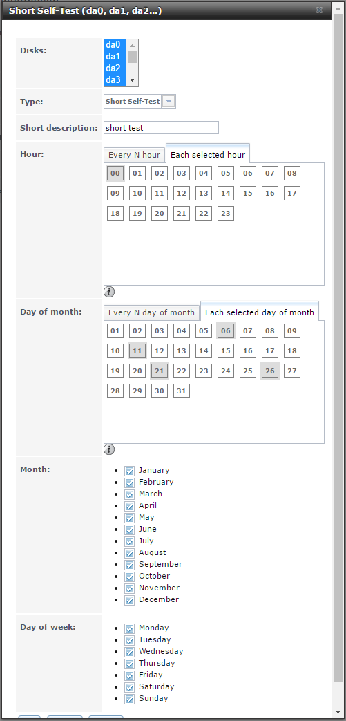
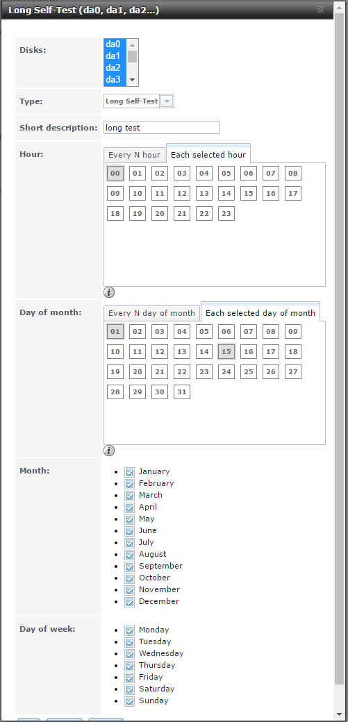
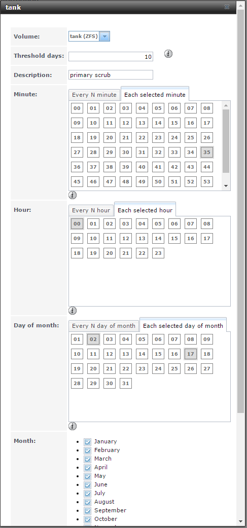
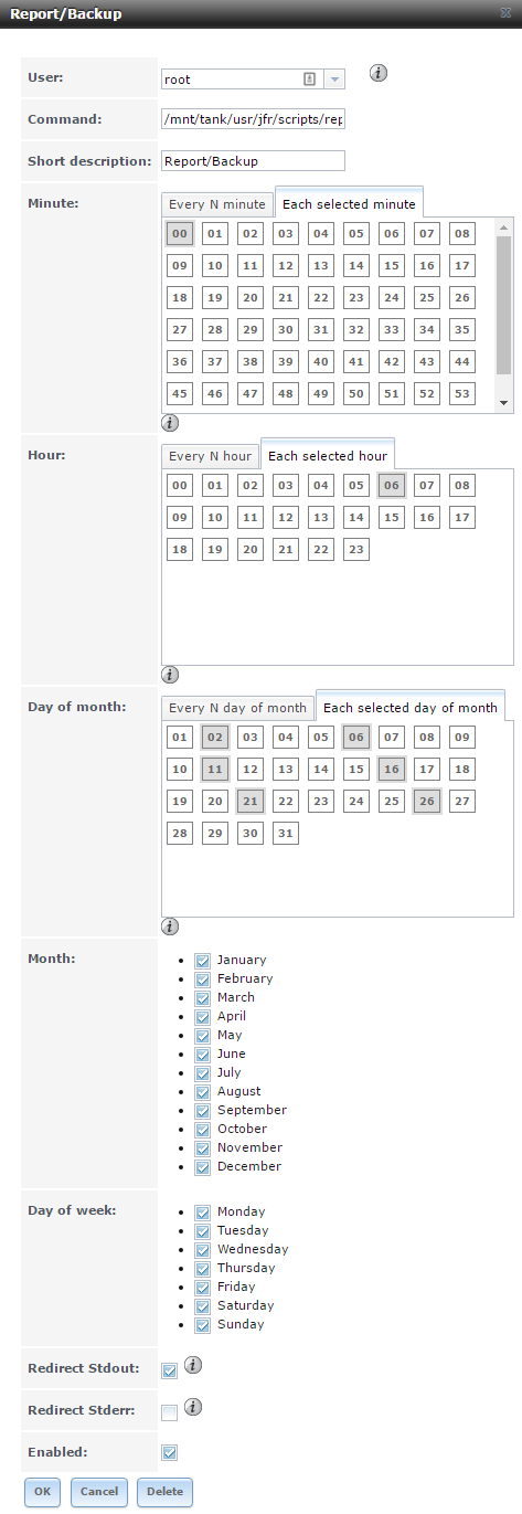
As I mentioned above, scheduling the SMART tests, scrubs, and email reports relative to each other is important. As an example, the table below shows what my cron schedule looks like. Each column is a different scheduled cron event, the rows represent the days of the month, and each cell has the time the event will run (in 24-hour format, so 00:00 is midnight, 06:00 is 6 AM). For those familiar with crontab basics, it's worth pointing out that you shouldn't edit the crontab directly as system reboots will reset it to whatever was set in the web UI.
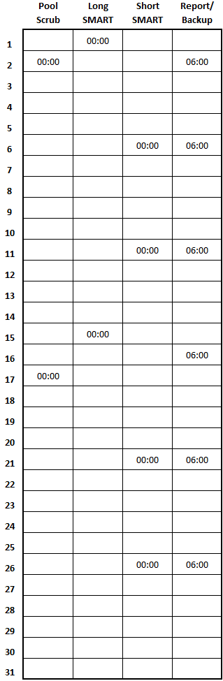
Configure fan thresholds in ipmitool. [2018 Update] As it turns out, setting your fan thresholds with ipmitool is unnecessary if you're using the fan script in the next section. If you properly configure the script with your minimum fan speeds, it will automatically set fan thresholds by calling ipmitool for you. This information might still be helpful to someone, so I'll leave it up. [Original Text] Setting the fan speed thresholds is important so the daemon controlling fan speed knows how high and low they can actually spin. The process might be a little different for different motherboards, but the following information is valid for Supermicro X10 series boards. This process can be a giant pain in the ass, but if you want a working fan control script, it’s an unfortunate necessity. If you don’t mind running your fans at 100% full time, you still need to set these values, but you can skip the fan control script and just change the fan control method in the IPMI interface. Most of the below information comes from a post on the FreeNAS forums. First, SSH into and get root on your FreeNAS machine, then run:
ipmitool sensor list all
The output should list all the sensors in your machine, the sensor values, units, health, and a set of threshold values. For the fans, the sensor values will be in RPM. The sensor thresholds can be rather cryptic, but they are as follows:
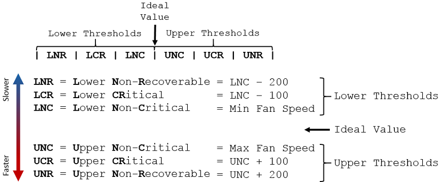
The system uses these thresholds to control fan speed based on system temperatures (which, you may notice, have their own set of thresholds) and the fan speed profile you have set in the IPMI web UI (which you don’t need to mess with as the fan control script in the next step actually sets the required profile value automatically).
Determine the minimum and maximum fan speed spec for all of your system fans, including any that might be mounted on the CPU cooler. These values are typically posted on the fan manufacturer’s website. If it is presented with +/- a certain percentage, subtract that given percentage to calculate the minimum speed and add that given percentage to calculate the maximum speed. For example, on the Noctua NF-F12 iPPC-3000, the minimum speed is listed as 750 RPM +/- 20% and the maximum speed is 3000 RPM +/- 10%. The minimum value I used for these fans is
750-(750*20%) = 600 RPM, and the maximum value I used is3000+(3000*10%) = 3300 RPM. Use these min and max values as your LNC and UNC, respectively. Note that impitool will round threshold values to the nearest hundred (i.e., 550 rounds up to 600, 540 rounds down to 500).Determine the LCR and LNR values by subtracting 100 and 200 from the LNC value, respectively. With those values, run the following command on SSH (pay careful attention to the sequence of numbers; they should GROW in value from left to right):
ipmitool sensor thresh "<sensor name>" lower <lnr> <lcr> <lnc>
Determine the UCR and UNR values by adding 100 and 200 from the UNC value, respectively. With those values, run the following command on SSH (again, pay careful attention to the sequence of numbers; just like before, they should GROW in value from left to right):
ipmitool sensor thresh "<sensor name>" upper <unc> <ucr> <unc>
Repeat the above steps for all fans in your system. Also note down all the threshold values for all fans as you will need them in the next step.
Set up fan control script. This script is also from the FreeNAS forums. This script assumes you have your cooling zones properly set (i.e., all HDD fans connected to the FANA header on your motherboard, all CPU fans connected to the FAN1 - FAN4 headers). This script is pretty slick, but I’ve been thinking of tinkering with it to make the speed changes ramp more gradually. [2019 Update:] This portion of my setup has changed quite a bit. I've rewritten Stux's Perl-based script in Python and added support for more fan zones. I also have the script sending the fan control commands to independent Raspberry Pi units in each chassis instead of to ipmitool. Lots more on this change in the expansion section below.
Get the script from here [.pl file] and put it somewhere on your server; I recommend somewhere in your primary login’s home folder.
Set the configuration parameters as needed (here is a listing just the parameters I modified; others I left default):
Debug: I had to do some initial troubleshooting with my parameters, so setting this to a higher value was useful at first. I run it at debug=1 now.
Fan Speeds: Take the UNC value from the section above for both your HDD fans and your CPU fans and enter them here.
CPU/HD Fan Duty Levels: My Noctua HDD fans can spin down to ~25% of max speed without stalling, so I changed duty_low to 25. Do the math on your fans and adjust as needed.
Test it by running the following command:
screen ./hybrid_fan_controller.pl
Watching the output and listen to the system fan speeds. It may take a minute or so to fall into the correct rhythm. If it doesn’t seem like it’s working, check the script settings and the fan thresholds in ipmitool. While troubleshooting, you might also find this simple script [.sh file] helpful. It's from the FreeNAS forums link in the previous section and it outputs all CPU and HDD temps.
If it’s working, create a new script file named “start_fanctrl” and paste the following into it (making sure to edit the directories in the last line):
#!/bin/bash
echo "Starting Hybrid Fan Controller..."
/<path to fan ctrl script>/hybrid_fan_controller.pl &>> /<path to fan control log>/fan_control.log &
Once that script is saved, go into the FreeNAS web UI and set it to run on startup. Go to Tasks > Init/Shutdown Scripts, click “Add Init/Shutdown Script”, set it to “Command”, enter the path to your
start_fanctrlscript (-NOT- to the larger perl script), and select “Post Init” for when.
Add system tunables for 10GbE networking. [2018 Update] There are several system tunables you should add to get 10GbE networking running at full speed. To add system tunables, go to System > Tunables (obtuse, I know...) and click 'Add Tunable'. Pay attention to the Tunable type. Most will be 'sysctl' tunables, but one is a 'loader'. If you're curious what each of these tunables actually do, check the blog post here on FreeBSD network tuning and optimization. The tunables you should add for 10GbE network are listed in the table below:
Variable Value Type cc_cubic_load YES loader net.inet.ip.intr_queue_maxlen 2048 sysctl net.inet.tcp.cc.algorithm cubic sysctl net.inet.tcp.inflight.enable 0 sysctl net.inet.tcp.recvbuf_auto 1 sysctl net.inet.tcp.recvbuf_inc 524288 sysctl net.inet.tcp.recvbuf_max 16777216 sysctl net.inet.tcp.sendbuf_auto 1 sysctl net.inet.tcp.sendbuf_inc 16384 sysctl net.inet.tcp.sendbuf_max 16777216 sysctl net.route.netisr_maxqlen 2048 sysctl
Setting Up SMB Sharing
With all the administrative and monitoring settings in place, I could move on to setting up some shares. This section will focus on SMB/CIFS-based shares because that’s what I use, but FreeNAS offers a wide variety of network file sharing protocols. On the subject of SMB/CIFS, Microsoft summarizes the common question “how are SMB and CIFS different” as follows: “The Server Message Block (SMB) Protocol is a network file sharing protocol, and as implemented in Microsoft Windows is known as Microsoft SMB Protocol. The set of message packets that defines a particular version of the protocol is called a dialect. The Common Internet File System (CIFS) Protocol is a dialect of SMB. Both SMB and CIFS are also available on VMS, several versions of Unix, and other operating systems.” The full article text is here. Samba also comes up a lot, which is an open-source *nix SMB server. It can do some other stuff too (related to Active Directory), but the Samba software isn’t really necessary as FreeNAS has built-in support for several SMB “dialects” or versions (including CIFS).
Getting network file sharing fully configured can be a pain, mostly due to permissions configuration. Because I only work with SMB shares, I do all my permissions management from my primary Windows 10 machine. The Windows machines in my environment (all on Win10) connect over SMB protocol version 3.1.1 (listed as SMB3_11 in smbstatus); the *nix and OS X machines in my environment connect on SMB protocol version NT1. I’ll provide some basic examples from my configuration, but SMB sharing can get very tricky very fast. If you get too complicated, it will become a giant pain a lot faster than it’s worth, so be forewarned. If you find yourself at that point, take a step back and think through possibly simpler ways to accomplish your goal.
Start by enabling the SMB service in the FreeNAS web UI (Services > Control Services).
Click the wrench icon to access the SMB service settings. Most of the default values are fine here, but I set a NetBIOS name (you probably want to use your FreeNAS hostname) and Workgroup (note the NetBIOS name and Workgroup can not be set to the same value). You may want to set aux parameters here or on the individual shares; I set them on the individual shares so I will cover them below. Read the Services > SMB section in the user guide before changing any of the other parameters on this screen.
Once the SMB service is enabled and configured, go to Sharing > Windows (SMB) Shares > Add Windows (SMB) Shares. Again, most of the default values are fine here for most applications. Here are the settings I changed:
Path: Enter the path to the dataset you created above (
/mnt/tank/britlibin my case).Name: I used my dataset name (
britlib) for my share name.Apply Default Permissions: This goes through the share path and recursively sets default permissions. It’s useful to leave this checked for the initial setup, but if you come back in to change any share settings, uncheck it so it doesn’t mess up any permissions changes you made.
Export Recycle Bin: I checked this so files I delete from the share are moved to a hidden .recycle directory in the root folder of the share (/mnt/tank/britlib/.recycle). Go in via SSH and delete this .recycle directory from time to time to free up disk space. If you leave this box unchecked, deleted files will be permanently removed immediately.
Auxiliary Parameters: I have a few of these set on my primary share. Here’s what I use (each parameter is explained below; see the smb.conf man page for more info:
veto files = /._*/.DS_Store/Thumbs.db/desktop.ini
delete veto files = yes
hide dot files = yes
ea support = no
store dos attributes = no
map archive = no
map hidden = no
map readonly = no
map system = no
veto files: This is a forward slash (/) separated list of files and directories that you would like to set as neither visible nor accessible. You can use*and?as wildcards. In this case, I veto any files starting with._and files named.DS_Store,Thumbs.db, anddesktop.ini. You can adjust your list as needed.delete veto files: Allows you to delete directories with vetoed files in them when you set this to ‘yes’.hide dot files: This controls “...whether files starting with a dot appear as hidden files.”ea support: “...Controls whether smbd(8) will allow net=clients to attempt to store OS/2 style Extended attributes on a share.” This is typically only enabled to support legacy systems, so I have it disabled. Note that this setting is not compatible with the streams_xattr VFS object, and is therefore not compatible with the "fruit" VFS object which is commonly used by Apple clients (thanks anodos on the FreeNAS forums for pointing this out!). See below for more details on this setting.store dos attributes: When this is set, “...DOS attributes will be stored onto an extended attribute in the UNIX filesystem, associated with the file or directory.” As above, typically only enabled to support legacy systems.map archive: “This controls whether the DOS archive attribute should be mapped to the UNIX owner execute bit.”map hidden: “This controls whether DOS style hidden files should be mapped to the UNIX world execute bit.”map readonly: “This controls how the DOS read only attribute should be mapped from a UNIX filesystem.”map system: “This controls whether DOS style system files should be mapped to the UNIX group execute bit.”
The last 6 settings come from the FreeNAS forums post here and are all set to ‘no’ with the goal of speeding up SMB access (specifically, while browsing directories). The first two are ‘no’ by default, but I have them set explicitly. If you have legacy devices or applications that need to access your SMB shares, you may need to set these to ‘yes’, but doing so could cause a performance penalty. Setting all of these parameters to ‘no’ will prevent SMB from using extended attributes (EAs), tell SMB not to store the DOS attributes (any existing bits that are set are simply abandoned in place in the EAs), and will cause the four DOS parameter bits to be ignored by ZFS.
Once I created the SMB share, I was able to mount it on another machine. In the following examples, I’ll show how to mount the share and manage permissions from a Windows 10 machine. To mount the share on Windows, open a new “My PC” window and click “Map network drive”. Select a drive letter and set the folder as
\\<server hostname or ip>\<smb share name>
Check “Reconnect at sign-in” if you want the share the be automatically mounted. You’ll likely also need to check “Connect using different credentials”. Once you hit “Finish” (assuming you checked “Connect using different credentials”), you’ll be prompted for connection credentials. Click “More choices”, “Use a different account”, set the username as \\<server hostname>\<the username you made in FreeNAS>, and enter your password. This will let you connect to the share with the credentials you created in FreeNAS rather than credentials stored on the Windows machine. If the username and password combination are exactly the same on FreeNAS and your Windows machine, sometimes you can get away with leaving the domain specification (the \\<server hostname>\ part) out of the username string, but it’s always best to be explicit.
Adjusting Permissions
With the share mounted, I could finally move some files in. As I mentioned before, everything that follows will be fairly specific to Windows 10, but you should be able to apply the same process to any modern Windows version. Once you have some data copied over, you can start adjusting the permissions on that data. Open the properties window for a directory and select the Security tab. The system will display a list of groups and user names and each of their respective permissions for this given directory (it may take a second to resolve the group IDs; be patient). You can adjust basic permissions by clicking the “Edit” button; a new window will pop up and you’ll be able to adjust or remove the permissions for each group or user and add new permission definitions. You may notice that the default set of permissions aren’t editable here; this is because they’re inherited from the parent folder (if the folder you’re looking at is in the share’s root directory, its permissions are inherited from the share itself; to adjust those permissions, open the properties window for the mounted share from the “My Computer” window and adjust its settings in the Security tab).
To adjust permissions inheritance settings for a file or folder (collectively referred to as a “object”), click the Advanced button in the Security tab of the object’s properties window. In this new window (referred to as the “Advanced Security Settings” window) you can see where each entry on the permission list (or “Access Control List”, ACL) is inherited from or if it is defined for that specific object. If you want to disable inheritance for a given folder, you can do so by clicking the “Disable inheritance” button on this window; you’ll then be able to define a unique set of permissions for that object that might be totally different from its parent object permissions. You can also control the permissions for all of this object’s children by clicking the check box “Replace all child object permissions...” at the bottom of the window. We’ll go through the process of adding a read/execute-only ACL entry for the services group to a given folder.
Open the Advanced Security Settings window for the folder you would like to allow the services group to access (Read/Execute only), click the Add button, click Select a principal at the top of the window (“principal” means user or group), type in services (or whatever user or group you want) and click Check Names. It should find the services group and resolve the entry (if it doesn’t, make sure you’ve actually added a services group in the FreeNAS web UI settings). You can adjust the “Type” and “Applies to” parameters if you like (each option is pretty self-explanatory), but I’m going to assume you’ve left them as the default values. Click “Show advanced permissions” on the right side of the window to view a full list of the very granular permissions that Windows offers. Each of these permissions options are also pretty self-explanatory, and most of the time you can get away with using just basic permissions (meaning you don’t click this “Show advanced permissions” button). For read/execute only, you’ll want to select the following advanced permissions:
Traverse folder / execute file
List folder / read data
Read attributes
Read extended attributes
Read permissions
If you click “Show basic permissions”, you will be able to see that this set of selections will translate to:
Read & execute
List folder contents
Read
You can leave the “Only apply these permissions...” check box unchecked. Go ahead and hit OK to be brought back to the Advanced Security Settings window where you’ll see your new ACL entry added to the list. It’s probably a good idea to check the “Replace all child object permission entries...” box to make sure everything within this folder gets the same set of permissions, but that’s obviously your choice. If you want to add or adjust other permissions, go ahead and do that now. When you’re happy with the settings, hit OK on the Advanced Security Settings window, hit OK on the folder properties window, and wait for it to go through and apply all the permission changes you just made. With the services group granted read/execute access to this folder, you should now be able to connect to it from another device (like a VM, as shown below) via any user in the services group. Once I had all my data moved into my SMB share, I went through and adjusted the permissions as needed by repeating the steps I outlined above.
I tend to prefer the Advanced Security Settings window (as opposed to the window you get when you hit the “Edit...” button in the Security tab) so I can make sure the settings are applied to all child objects, and the Advanced Security Settings window really isn’t any more difficult to use that the standard settings window. For more info on how to set up SMB share permissions, watch these videos in the FreeNAS resources section.
One final note here before moving on: if you want to grant a user permissions (whether it be read, execute, or write) to access some file or folder deep in your share’s directory structure, that user will also need at least read permissions for every parent folder in that structure. For example, if you want to grant the user “www” permission to access the directory “httpd” at location //SERVER/share/services/hosting/apache24/httpd, the user “www” will need to have read permission for:
//SERVER/share//SERVER/share/services//SERVER/share/services/hosting//SERVER/share/services/hosting/apache24
...or else he won’t be able to access the “httpd” folder. In this scenario, you can see how useful automatic inheritance configuration can be.
Setting Up iSCSI Sharing [2018 Update]
iSCSI is a block-level sharing protocol that serves up a chunk of raw disk space. We can mount this raw disk space on the client format it with whatever file system we want; the client sees it as a physical disk connected directly to the system. Block-level sharing protocols like iSCSI and Fibre Channel differ from file-level sharing protocols like SMB/CIFS, NFS, and AFP in that the server has no notion or understanding of the file system or files that the client writes to the disks. Because block-level protocols operate at a lower level, they tend to perform much better than file-level protocols. Because the server has no concept of the file system on the share, it doesn't have the ability to lock in-use files and prevent simultaneous conflicting editing like SMB can do. For that reason, iSCSI shares are typically mounted on only a single machine. Because it has low protocol overhead and good performance, iSCSI is a very popular choice for serving up storage to virtual machines. You should strongly consider using iSCSI over SMB or NFS for applications that will be very sensitive to latency, IOPS, and overall storage throughput.
Before we dive into configuration, it's worth going over some iSCSI nomenclature. iSCSI is a protocol for sending SCSI (pronounced "scuzzy") commands over an IP network. The iSCSI host creates a target that a client can mount. A target is a block of disk space that the host sets aside. A target could be the entire data pool, or a small chunk of it. A single iSCSI host could have many targets on it. The target refers to its storage via a Logical Unit Number or LUN. For this reason, you'll sometimes hear 'target' and 'LUN' used interchangeably. The iSCSI client is referred to as an initiator (or more specifically, the software or hardware they're using to connect to the target is the initiator). A client connects to the iSCSI storage via the server's portal. The server's portal specifies the IP and port the service will listen on as well as any user authentication used. FreeNAS adds an extra step called an extent that configures a zvol or a file on a file system as something that can be served up by iSCSI.
On ZFS, we set aside a chunk of disk space using a zvol. A zvol can be created as a child of a file system or clone dataset; a zvol can not be created as the root dataset in a pool. In the example below, I walk through creating a zvol on my primary storage pool and then serve up that zvol via iSCSI. We'll set up an iSCSI portal, then configure a set of allowed initiators, then create a target, then configure an extent, and finally we'll map that extent to the target we created. I'll also show how to mount the iSCSI share on Windows (e.g., configure the initiator) where I'll use it to store my Steam library.
In FreeNAS, we can add a zvol by going into the storage manager, selecting the dataset we want to contain the zvol, and clicking the 'Create zvol' button at the bottom of the window. Here is an explanation of the options on the 'Create zvol' window:
zvol name: Enter a simple name. I called mine 'britvol' which we'll use later in the example.
Comments: Optional, I left this blank.
Size for this zvol: zvols are (typically) a fixed size. Enter size with suffixes like 'M', 'G', 'T', etc. I set mine to '5 T'.
Force size: If the space you entered above causes to total free space on the pool to drop below 20%, the operation will fail. Check this box to force the operation in that case.
Sync: How to handle sync writes. Recommend that you leave it on 'Standard'.
Compression level: Even though it can't see the files, ZFS still compresses the data on zvols. Recommend that you leave this on 'lz4'.
ZFS Deduplication: ZFS can also dedupe zvols but it incurs a very significant performance penalty. Recommend that you leave this disabled.
Sparse volume: If you leave this unchecked, ZFS will immediately reserve the full size of the zvol on your pool. If you check this, it's possible you could fill the pool and have iSCSI clients think they can still write data. If you do decide to check this, just be careful about your pool utilization. I checked this because my system is fairly simple and it's easy for me to stay on top of the pool utilization.
Block size: Unlike file system datasets, zvols use a fixed block size to store data. Select that block size here but be mindful of how that block will be split up on RAID-Z vdevs (refer to the allocation overhead section above.) I set mine to 32K; this will give me partial stripes but no padding sectors. None of the options would allow me to totally avoid allocation overhead, but that's okay.
With the zvol successfully created, we can start working on the iSCSI setup. Start by clicking Sharing > Block (iSCSI) > Target Global Configuration. You can either leave the default base name (iqn.2005-10.org.freenas.ctl) or specify your own. Technically, you can put whatever you want here, but if you want to comply with the various iSCSI RFCs, you should use the following format: iqn.yyyy-mm.domain:unique-name where domain is the reverse syntax of the domain on which the iSCSI host resides, yyyy-mm is the date that domain was registered, and unique-name is some unique identifier for iSCSI host. For example, if I host my iSCSI server on iscsi.jro.io and I registered that domain in August of 2015, I should use iqn.2005-08.io.jro.iscsi:freenas as my base name. I don't use that as my base name because all of this seems very silly to me, but I'm sure that someone somewhere at some point had a seemingly valid reason for writing this specification. In any case, we press onwards... You can leave the ISNS Servers and "Pool Available Space Threshold (%)" fields blank. The threshold field can be used to trigger a warning if the pool holding your zvol extent gets too full. Note the pool will always trigger a warning at 80% regardless of what you put here, so it's not really necessary.
The next step is to create an iSCSI portal. Expand the 'Portals' menu and click 'Add Portal'. Add a comment to your portal to easily identify it later. I left the authentication options set to 'None' because my system is on a private home network, but if you're using iSCSI in a different type of network, you may need to do some research on how to configure authentication. Select your server's IP address from the IP drop-down menu, leave the port on its default value (3260), and click 'OK'.
Next, expand the 'Initiators' menu and click 'Add Initiator'. If you want to limit access to your iSCSI share to specific initiators or IPs/networks, you can do so here. I left both values as 'ALL', put in a descriptive comment, and hit 'OK'.
After your portal and set of allowed initiators is configured, you can configure your target. Expand the 'Targets' menu and click 'Add Target'. Enter a descriptive name and alias (they can be the same) and select the portal and initiator you just created. As above, I left the authentication-related fields as 'None'. Click 'OK' when you're done.
Now we can create an extent. Expand the 'Extents' menu and click 'Add Extent'. Enter a descriptive name and make sure 'Device' is selected for 'Extent Type'. You can create an extent (and thus an iSCSI target) backed by a file on a file system rather than a zvol, but I'm not aware of any use case where this would be advantageous. Select the zvol you created in the 'Device' drop down and leave the serial number default. Some iSCSI initiators (including the one on Xen Server) have trouble mounting iSCSI targets if the logical block size isn't 512 bytes. For that reason, selecting '512' is recommended for the 'Logical Block Size' field for compatibility, but you can select '4096' if you know your initiator can support it. I went with '4096'. The rest of the fields on this menu can be left alone in most cases. Mouse over the 'i' icons for more information on them if you're curious what they're for. Click 'OK' when you're done.
Next, we'll map the extent to the target we created. Expand the 'Targets / Extents' menu and click 'Add Target / Extent'. Select the target and extent you created, leave the 'LUN ID' field set as 0 and click 'OK'.
Finally, the iSCSI service must be enabled in the Services > Control Services menu. You should also check the 'Start on boot' box. Now we can move over to our Windows machine and get the iSCSI share mounted!
On Windows, you will need to start the iSCSI Initiator program from Microsoft. If your start menu search doesn't pull up any results, you can download and install the software from here. In the initiator program, click the 'Targets' tab, then enter the IP of your server in the 'Target:" field at the top and hit 'Quick Connect'. The program will pop up a new window with the targets it discovered at that address. Select the target you created and click 'Connect'. (Note, if you enabled user authentication, you'll get an error here. You will have to use the 'Connect' button towards the bottom of the main window and click the 'Advanced...' button to enter access credentials.) On the main window, it should list the base-name of your target and specify 'Connected' in the status column. Click 'OK' then start up the Windows Disk Management program. From here, you can initialize and format the disk just like you would any physical SATA disk in Windows. Once it's formatted, it will show up on your system and you can start copying data to it. On the FreeNAS side, you can still run snapshots on the zvol, but you won't be able to access the files directly without mounting it.
As I noted above, you can create multiple iSCSI targets on a single server. If you want to add more iSCSI targets, start by creating another zvol, then skip directly to the target configuration steps. Set up a target, an extent, and then map that extent to your target. From there, you can mount the new target on your client.
Performing Initial bhyve Configuration
Running virtual machines on a storage system is kind of a controversial subject (as you’ll quickly discover if you ask anything about running a bhyve in #freenas or the forums). In a business environment, it’s probably a good idea to have a dedicated VM host machine, but for personal use, I don’t see it as a huge risk. The VM manager (also called a “hypervisor”) I use is called bhyve (pronounced “beehive”, super-clever developers...). More information on bhyve can be found here. It’s native on FreeNAS 9.10+ and setting it up and managing bhyve VMs (simply called “bhyves”) is very easy. There’s a great video on the basics of bhyve setup here (from which I am going to shamelessly copy the following steps).
Before we get started, make sure you know the name of your pool (called “tank” if you’re following this guide verbatim) and the name of your primary network interface (which you can find by going to the web UI and looking at Network > Network Summary; mine is igb0, highlighted in yellow below).
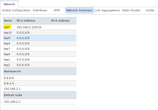
Once you’ve got that information, SSH into your server and run the following command as root to set up bhyve (replacing the <pool name> and <network interface> parts, obviously):
iohyve setup pool=<pool name> kmod=1 net=<network interface>
It will return some information to let you know it’s created a new dataset on your pool (to house VM data) and set up a bridge between the provided network interface and the virtual interface that your VMs will use. The kmod=1 flag tells bhyve to automatically load the required kernel modules. This program iohyve will be what you use to manage all your bhyve VMs. You can run iohyve (with no arguments) to see a summary of all available commands.
After you run the above command, go into the FreeNAS web UI and go to System > Tunables > View Tunables. You’ll need to add two new tunables which will ensure that the bhyve settings you just configured above are re-applied when FreeNAS reboots. Click the Add Tunable button and enter the following settings:
Variable: iohyve_enable
Value: YES
Type:
rc.confComment: (Leave blank if you want)
Enabled: Checked
Click OK and then add a second tunable with the following settings (make sure to change the network interface value):
Variable: iohyve_flags
Value:
kmod=1 net=<network interface>Type: rc.conf
Comment: (Leave blank if you want)
Enabled: Checked
Click OK and you’re all set; you’re now ready to install some bhyve VMs!
Creating a bhyve VM
Before we get into installing a bhyve, it will be useful to list out some of the more commonly used iohyve commands (most of which need to be run as root):
Viewing bhyve info:
iohyve list: Lists all bhyve VMs.iohyve info [-vs]: Gets more detailed info on bhyve VMs; -vs flags are useful too.iohyve getall <guest name>: Gets the value for all properties in a bhyve.
Creating bhyve VMs:
iohyve create <name> <disk size>: Create a new bhyve. For disk size, you can use theMorGsuffix (i.e.,4096Mor4G).iohyve set <name> <property>=<value> [<property2>=<value> ...]: Set property values for a bhyve, like the number of CPUs it can use, or amount of RAM it can access; can set multiple properties in one command.iohyve fetchiso <URL>: Download an ISO for bhyve installations.iohyve isolist: List all ISOs you can use for creating bhyve installations.iohyve install <name> <iso>: Install<iso>on selected bhyve; for some installations, console will appear to hang; you will have to open a new SSH session and use the console command (see below).iohyve console <name>: Connect to the console of selected bhyve, sometimes required for new VM OS installation.
Manage bhyves:
iohyve start <name>: Boot up selected bhyve.iohyve stop <name>: Shut down selected bhyve.iohyve delete [-f] <name>: Delete selected bhyve; add -f flag to force the operation.iohyve forcekill <name>: Force shut down selected bhyve; useful if it’s stuck on the bootloader.
Frequently-used bhyve Properties (set with
setcommand, view withgetcommand):name=<name>: Name of bhyve VM.boot=[0|1]: Start bhyve on host system reboot?cpu=<# of threads>: Number of CPU threads bhyve can access.ram=<amount of memory>: Amount of memory bhyve can access; you can use theMorGsuffix (i.e.,4096Mor4G).loader=<boot loader>: Boot loader to use; example will usegrub-bhyve.os=<os name>: Name of OS to be used; example will usedebian.description=<text>: bhyve description; optional.
I’ll go through a basic example of installing a Debian bhyve guest (or VM; I’ll use the terms “bhyve”, “guest”, and “VM” interchangeably in this section) and mounting shares from your NAS on the VM so it can access data. The first thing you will want to do is download an ISO with the iohyve fetch command. Note that this is the only (simple) way to use a given ISO to install an OS. I use the Debian amd64 network installation ISO, which you can find here. Don’t download the ISO in your browser, but rather copy the URL for that ISO (for amd64 Debian 8.7.1, it’s at this link) and run the following command on your FreeNAS machine as root:
iohyve fetchiso <paste URL to ISO>
Wait for it to download the ISO file from the provided link. When it’s done, we can create the VM. For this example, I’m going to create a guest named “acd” (Amazon Cloud Drive) which we’ll use later to set up rclone for full system data backups. I’ll give it 5GB of disk space, 2 CPU threads, and 2GB of RAM. You can change the name, CPU threads, or RAM values later, but note that changing the disk space of the guest later on can cause issues (even though there is an iohyve command for it; check iohyve man page). When you’re ready, run the following commands:
iohyve create acd 5G
iohyve set acd ram=2G cpu=2 os=debian loader=grub-bhyve boot=1
The first command will create a new bhyve guest called acd with a 5GB disk. The second command will set the listed properties for that bhyve (2GB RAM, 2 CPU threads, debian-based OS, GRUB bootloader, auto-boot enabled). The next step is to install the Debian ISO on this bhyve guest. Get the name of the ISO file by running the following:
iohyve isolist
Copy the name of the listed Debian iso, then run the following:
iohyve install acd <paste ISO name>
The console will appear to hang, but don’t panic! As the terminal output message will tell you, GRUB can’t run in the background, so you need to open a second SSH session with your FreeNAS machine. Once you’re in (again) and have root, run the following command in your second terminal session to connect to the acd console:
iohyve console acd
This will drop you into the console for your new VM (you may have to hit Enter a few times) where you can go through the Debian installation. Follow the instructions, selecting a root password, new user (for this one, I’d suggest “acd”), and hostname when prompted. Make sure that when you get to the package selection screen, you unselect all desktop environment options and select the SSH server option. Other than that, the Debian installation process is pretty easy. When you’ve finished, the VM will shut itself down and you can close out of this second SSH window. If you ever have to use iohyve console for other purposes, you can exit it by typing ~~. or ~ Ctrl+D.
Back in your first SSH session, the terminal should be responsive again (you may have a few errors saying stuff about keyboard and mouse input but you can safely ignore those). Run the following command to start the bhyve VM back up:
iohyve start acd
While you’re waiting for it to boot back up, take a moment to create a new user in the FreeNAS web UI (Account > Users > Add User). Give it whatever user ID you want, but make sure the username and password are exactly the same as the user you created on your bhyve VM. I would also suggest unchecking “Create a new primary group for the user” and selecting the “services” group you created above as this user’s primary group.
By now, the bhyve VM should be fully booted (typically it only takes 15-30 seconds), so SSH into this new VM with the non-root user account you created; you may need to look at your router’s DHCP tables to figure out its assigned IP address. Once you’re in, you’ll want to run su to get root then update software through apt-get or aptitude and install any standard programs you like (like sudo, htop, ntp, and whatever else you might need). Once sudo is installed and configured (if needed, use Google for help), exit back out to your primary user. The next step will be to mount your SMB share from FreeNAS on your bhyve VM. Most of the following steps are based on this guide from the Ubuntu wiki and a couple folks from the FreeNAS forums (thanks Ericloewe and anodos!).
The first thing you need to do is install the cifs-utils package by running:
sudo apt-get install cifs-utils
I usually mount my shares in the /media directory, so go ahead and create a new directory for your share (I’ll use mountdir in this example, but you can call it whatever you want):
sudo mkdir /media/mountdir
Next, you will want to create a text file with the login credentials for your VM user. Run the following command to create and open a new text file in your user’s home directory (I use nano here, but use whatever editor you like):
nano ~/.smbcredentials
In this file, you will want to enter the following two lines of text. I’ll use “acd” as the username and “hunter2” as the password for the example, but obviously change the text in your credentials file. Make sure it’s formatted exactly as shown; no spaces before or after the equal signs:
username=acd
password=hunter2
Save and exit (for nano, Ctrl+O to save, then Ctrl+X to exit) then change the permissions on this file:
chmod 600 ~/.smbcredentials
Next, you’ll want to run the following command to edit the fstab file (the file system table) on your bhyve with root privliges:
sudo nano /etc/fstab
Add the following line at the bottom of the file, making sure to replace the <server name>, <share name>, and <user name> placeholders with the appropriate values for your system (obviously, leave out the <>; if you named your mount point in the /media directory something different, make sure to change that, too):
//<server name>/<share name> /media/mountdir cifs uid=<user name>,credentials=/home/<user name>/.smbcredentials,iocharset=utf8,sec=ntlmssp 0 0
Sorry about the super-long, table-breaking statement; there's probably a way to split the above into two shorter lines, but whatever... Save and exit (for nano, Ctrl+O to save, then Ctrl+X to exit). Once you’re back at the command line, run the following to attempt to mount the share:
sudo mount -a
If it goes through, try to access the share and list its contents:
cd /media/mountdir
ls
If it prints out the contents of your share, you’re all set! If it throws an error, check the permissions on your share, check that the credentials is entered correctly on FreeNAS and in the ~/.smbcredentials file, and check that the VM can resolve the server name to the correct IP (if not, you may have to enter the IP in the mount string you wrote in the fstab file). Mounting shares and getting their permissions set up right can be extremely finicky, so anticipate at least a few issues here.
You can mount more than one share (or multiple points from a single share) by entering more than one line in the fstab. For example, if you wanted to mount //SERVER/share/photos and //SERVER/share/documents, you would enter both those lines in /etc/fstab:
//SERVER/share/photos       /media/photos       cifs    uid=user,credentials=/home/user/.smbcredentials,iocharset=utf8,sec=ntlmssp 0   0
//SERVER/share/documents    /media/documents    cifs    uid=user,credentials=/home/user/.smbcredentials,iocharset=utf8,sec=ntlmssp 0   0
Remember to create the /media/photos and /media/documents directories beforehand (otherwise you’ll get an error when you run the mount -a command).
Once the share is mounted, you’ll be able to access it in the bhyve’s file system as normal. If your user only has read permissions, you’ll obviously get an error if you attempt to modify anything.
Configuring rclone in a bhyve
[8/7/17 Note] Amazon Cloud Drive has banned the rclone API key, effectively breaking rclone's support for ACD. People on the rclone forums have posted workarounds, but I haven't tried any of them. The information below is still applicable to setting rclone up with any other remote. Check the rclone docs for detailed instructions on your specific remote.
The last topic I want to cover is the installation and configuration of rclone, which will help keep your data backed up in an Amazon Cloud Drive (ACD). rclone also allows you to encrypt all your data before it’s sent to ACD, so you don’t have to worry about Amazon or the Stasi snooping in on your stuff. ACD is a paid $60/yr service through Amazon.com that offers unlimited data storage, and unlike services like Backblaze and CrashPlan, you can get great upload and download speeds to and from their backup servers. rclone is a program that will connect with your ACD instance (via Amazon-provided APIs), encrypt all your data, and synchronize it with the backup servers. rclone is still in active development, so it can be a bit finicky at times, but hopefully this guide will help you get through all that.
Before we dive in, a quick word on the backup services market. If you don’t want to pay $60/yr, I would understand, but I would still strongly recommend some sort of backup mechanism for your data. For larger amounts of data, services that charge per GB can get very expensive very quickly, so I would recommend a service with unlimited storage. Other than ACD, the two best options are Backblaze and CrashPlan, both of which I used for at least several months (CrashPlan for a couple years). My primary issue with Backblaze was the upload speed; even after working with their support team, I was only able to get upload speeds of 50-100KB/s. If I only wanted to back up my most important ~2TB of data, at 100KB/s it would take nearly a year to get everything copied to their servers. I also used CrashPlan for about 2 years before building my NAS. The upload speeds were slightly faster than Backblaze (I was able to get ~1MB/s), but still not great. My biggest issue is the backup client’s huge memory consumption. The Java-based CrashPlan client consumes 1GB of RAM per 1TB of data you need to back up, and this memory is fully committed while the client is running. For a large backup size, this is obviously unacceptable. The client itself is also a bit finicky. For example, if you want to back up more than 1TB, you have to manually increase the amount of memory the client can use by accessing a hidden command line interface in the GUI. The final nail in the coffin of CrashPlan and Backblaze (at least for me) is the fact that they are both significantly more expensive than ACD. ACD is not without its issues, as we’ll see in the subsequent sections, but it seems to be the best of all the not-so-great options (granted, at a few dollars a month for unlimited data storage, expectations can’t be all that high).
Of course the first thing you’ll need to do is sign up for ACD, which you can do here. You get 3 months free when you sign up, so you have plenty of time to make sure the service will work for you. (Note that the Prime Photos service is not what you’re looking for; that only works for pictures.) Don’t worry about downloading the Amazon-provided sync client as we will be using rclone as our sync client. The instructions for setting up rclone are based on a guide (originally posted on reddit) which can be found here.
Start by SSHing into the bhyve VM you created in the previous step. You’ll want to make sure sudo and ntp are installed are configured. Run the following commands to download (via wget) rclone, unpack it, copy it to the correct location, change its permissions, and install its man pages:
wget http://downloads.rclone.org/rclone-current-linux-amd64.zip
unzip rclone-current-linux-amd64.zip
cd rclone-*-linux-amd64

sudo cp rclone /usr/sbin/
sudo chown root:root /usr/sbin/rclone
sudo chmod 755 /usr/sbin/rclone

sudo mkdir -p /usr/local/share/man/man1
sudo cp rclone.1 /usr/local/share/man/man1/
sudo mandb
The official rclone documentation recommends placing the rclone binary in /usr/sbin, but by default, the /usr/sbin directory isn’t in non-root users’ path variable (meaning a normal user can’t just run the command rclone and get a result, you would have to either run sudo rclone or /usr/sbin/rclone; more information on /usr/sbin here). You can either choose to run rclone as root (sudo rclone or su then rclone), type out the full path to the binary (/usr/sbin/rclone), or add /usr/sbin to your user’s path variable. I got tired of typing out the full path and didn’t want to have rclone running as root, so I added it to my path variable. You can do this by editing the ~/.profile file and adding the following line to the end:
export PATH=$PATH:/usr/sbin
This probably isn’t within the set of Linux best practices, but this user’s sole purpose is to run rclone, so I don’t see a huge issue with it.
[Updated 8/17/17]The next step requires you to (among other things) authorize rclone to access your ACD via OAuth. OAuth requires a web browser, but if you select the correct option during the setup, the rclone config script will give you a URL you can access on your desktop rather than having it try to open a browser on the server. To start the process, run the following command in your rclone machine's terminal:
rclone config
You should see the rclone configuration menu. Press n to create a new remote and name it; I named mine acd, which is what I’ll use in this guide. On the provider selection section, choose Amazon Drive (which should be number 1 on the list). You can leave client_id and client_secret blank. When prompted to use the auto config, say no. Follow the URL and you’ll be prompted for your Amazon login credentials then asked if you want to trust the rclone application (say “yes”). The website might prompt you for a string of characters; copy them from the rclone terminal and it should advance automatically to the next section. If everything looks ok, enter y to confirm and you’ll be brought back to the main rclone config menu where you can type q to quit.
The process for setting up encryption for your ACD remote connection is a little counter-intuitive, but bear with me; this is the official (and only) way to do it. It will initially appear that you’re creating a second remote connection, but that’s just the process for configuring encryption on top of an existing remote connection.
Back in the SSH session with your acd bhyve, run rclone config again. At the menu, type n to create a new remote, and name this new remote something different than your previous remote. For this example, I’ll use acdCrypt as the name for the encrypted version of the acd remote. On the provider selection screen, pick Encrypt/Decrypt a remote (which should be number 5). You’ll be prompted to enter the name of the remote you want to encrypt; if you named your previous remote “acd”, then just enter acd: (include the colon on the end). When prompted to choose how to encrypt the filenames, enter 2 to select “Standard”. You’ll then be prompted to pick a password for encryption and another password for the salt. I recommend letting rclone generate a 1024 bit password for both items; just make sure to copy both of them somewhere safe (I copied them to a text file on my desktop, archived the text file in a password-protected RAR archive, and uploaded the RAR file to my Google Drive). After you’re done with the passwords, enter y to confirm your settings and then q to exit the rclone configuration menu.
rclone should now be configured and ready to use, but before you start your first backup, it’s a good idea to configure rclone to run as a service so it automatically starts up on boot. We’ll do this by creating a systemd unit file for clone. The guide I followed for this process can be found here.
Before we create the service itself, run the following to create an empty text file in your user’s home directory (which we’ll need later on):
touch ~/acd_exclude
Start by creating a new services file and settings its permissions:
sudo touch /etc/systemd/system/acd-backup.service
sudo chmod 664 /etc/systemd/system/acd-backup.service
Open this new service file in a text editor, paste the following text into the file, then save and exit (Ctrl+O, Ctrl+X in nano; be sure to edit your share’s mount directory and the path for the log file):
[Unit]
Description=rclone ACD data backup
After=network.target

[Service]
Type=simple
User=acd
ExecStartPre=/bin/sleep 10
ExecStart=/usr/sbin/rclone sync /media/mountdir acdCrypt: \
	--exclude-from /home/acd/acd_exclude \
	--transfers=3 \
	--size-only \
	--low-level-retries 10 \
	--retries 5 \
	--bwlimit "08:30,10M 00:30,off" \
	--acd-upload-wait-per-gb 5m \
	--log-file <path to log file> \
	--log-level INFO

[Install]
WantedBy=multi-user.target
You’ll likely want to tune the parameters called with rclone for your own application, but this should be a good starting point for most people. Full documentation on all commands and parameters is available on the rclone website here. Here is a quick explanation of each parameters I set above (note the \ characters allow the lengthy command string to span multiple lines):
sync <sorce> <destination>: Tells rclone to sync from (in our case, the share we mounted earlier) to the (the encrypted remote we set up). Sync will delete files in the destination that are removed from the source; you can use copy here instead if you don’t want it to do that.exclude-from <text file>: Excludes files and paths matching the entries in this file, see here for details.transfers <#>: Number of simultaneous uploads to run, default is 4.size-only: rclone normally verifies transfers by checking both the file modification date and its file size, but ACD does not have an API call that allows rclone to get the modification date. This flag explicitly instructs rclone to only use the file size information. Without this flag, rclone still detects its working with ACD and doesn't attempt to pull file modification dates, so it isn't strictly necessary. (I originally had rclone set to use --checksum, but this doesn't work with an encrypted remote. Thanks /u/martins_m from reddit for catching this mistake!)low-level-retries <#>: ACD transfers tend to crap out pretty often for no apparent reason, so this (and the retries flag below) tells rclone to keep trying the transfer.retries <#>: Same as above.bwlimit <string>: Limits the upload bandwidth based on the schedule; my schedule limits uploads to 10MB/s from 8:30am to midnight and lets it run at full speed overnight.acd-upload-wait-per-gb <time>: From the rclone docs: “Sometimes Amazon Drive gives an error when a file has been fully uploaded but the file appears anyway after a little while.” This tells rclone to wait for a certain period of time (per GB) after the upload finishes for the file to appear. If the file doesn’t appear after that time period, rclone reports the transfer as an error.log-file <path>: Stores everything to a log file at the specified location rather than printing to screen.log-level <ERROR|NOTICE|INFO|DEBUG>: Selects verbosity of log. If you’re having issues, it might be worthwhile to switch to DEBUG.
I also have the service set to sleep 10 seconds before starting rclone to make sure the SMB share has time to mount. I would highly recommend reading through the rclone documentation (linked above) to figure out which settings would be appropriate for your use case. My filter file (acd_exclude) includes a list of directories and files I want rclone to ignore. Once you’ve got everything set in the acd-backup.service file, run the following command to enable the service so it runs on system start:
sudo systemctl enable acd-backup.service
After that, you can tell systemd to reload its daemons (you’ll need to run this command again any time you make changes to the acd-backup.service file):
sudo systemctl daemon-reload
You can start your service with the following command:
sudo systemctl start acd-backup.service
If you ever need to stop the service, you can run the following:
sudo systemctl stop acd-backup.service
Note that even though you stop the service, it may not terminate the rclone process; run htop to check and terminate any running processes to completely stop everything (useful if you want to update the parameters rclone is using via the service file).
You can follow along with rclone’s process by viewing the log file (in the location you specified in the acd-backup.service file). You can also use the following commands to see a summary of whats been uploaded:
rclone size <remote>: Shows the total number of files in the remote and its total size. This also works with sub-directories on the remote (seperated by a " : "), i.e.,rclone size acdCrypt:Photosto view the Photos directory in the acdCrypt: remote.rclone ls <remote>: Works similar to the Unix ls command, but lists everything in sub-directories as well. As above, you can specify a sub-directory, i.e.,rclone ls acdCrypt:Photosto list all photos rclone has uploaded.
You’ll have to use the log file and these two commands to view the progress of an encrypted upload; if you try to view your files on the ACD website (or using the mobile app), all the filenames will appear as garbled text.
The final thing you may consider doing is adding an entry in the root user’s crontab to restart the rclone service should it ever fail or exit. You can do this by running the following:
sudo crontab -e
Add the following line to the end of the file:
0 * * * * /bin/systemctl start acd-backup
Save and exit (Ctrl+O, Ctrl+X) and you’re all set. This will tell the system to start the acd-backup service on 60 minute intervals; if the service is already started, no action will be taken. If the service stopped, it will automatically restart it. As I noted above, ACD can be finicky sometimes, so some upload errors (particularly for larger files) are normal. With this cron statement, rclone should automatically retry those uploads after it’s finished its initial pass on your share (rclone is set to terminate after it finishes a full pass; this cron statement will re-invoke it, causing it to check the remote against your share and sync any changes).
Expanding Beyond a Single Chassis [2019 Update]
When I originally designed and built this system, I never expected to outgrow 100TB of storage. Despite that, data seems to have a way of expanding to occupy whatever space it's in, and so in late 2018, the time for a system expansion finally arrived. Unfortunately, I had used all 24 drive bays in my chassis (including the internal spots for SSDs). So what does one do in this situation? Did I need to simply build a second full FreeNAS system and somehow cluster them together to provide one logical storage volume? That was my original thought when I first built the system. We hear about "clusters" in enterprise computing all the time, so clearly that's was the answer.
As I've learned since I originally built this server, ZFS is not actually a clusterable file system, meaning it isn't capable of being distributed amongst an arbitrary number of storage nodes (or at least not natively). Examples of distributed file systems include DFS, Ceph, and Gluster. These file systems are said to "scale out", while ZFS "scales up". "Scale up" just means you attach additional disks directly to your system. But this brings me back to the previous question-- what am I supposed to do when my chassis is already full?
As it turns out, the answer is to add an expansion shelf! This is also sometimes called a JBOD (short for "just a bunch of disks"). It’s essentially another chassis with a bunch of drive bays and its own power supply. It doesn't need its own motherboard or CPU or memory or NIC or HBA or any of that other expensive stuff. You can connect the expansion shelf to the main chassis (or "head unit") with a host bus adapter ("HBA") that has external SAS ports. These external ports are functionally (and I believe electrically) identical to the internal ports on a normal SAS HBA except that they are located on the card's rear I/O shield rather than inside the chassis. You use an external SAS cable that has extra shielding and comes in lengths of up to 10 meters to attach the expansion shelf to this external HBA. The cable runs from the SAS port on the external HBA in the head unit to a passive external-to-internal SAS adapter mounted in a PCI bracket on the shelf and then from the adapter to the backplane in the shelf via an internal SAS cable. The drives in the shelf are powered by the shelf's own PSUs, so extra power load on the head unit isn't an issue. The FreeNAS system sees the drives in the shelf as if they were installed right inside the primary chassis with no extra configuration required.
While the basic idea is pretty straightforward, the execution of this expansion can be a bit tricky. I ran into some problems I had to solve before I could get the system running the way I wanted, namely:
Issue 1: In my primary chassis, I have 3 PCIe SAS HBAs, each with 2 SAS cables connected to the chassis’ backplane to support the 24 drives; am I going to need 3 more HBAs and 6 external cables to support 24 drives in a second shelf?
Issue 2: How do I turn on the power supplies in the expansion shelf when the head unit turns on?
Issue 3: If I do the same cooling and fan mods in the expansion shelf, how do I control those fans based on the temperature of just the disks in that shelf?
Overarching these three problems, I also needed to consider how to design things so I can scale beyond a single shelf down the road. I’d like to be able to support 5+ shelves if I need to.
PCIe Slot Count Issue
We'll start with the issue of PCIe slots and SAS connections. While adding another 3 PCIe HBAs to support 24 more drives might be possible on some systems, it isn't really practical to scale things beyond a single shelf in this manner. I might have been able to find a CPU and motherboard that support 6 PCIe x8 slots, but if I ever managed to outgrow the single expansion shelf, I would likely have a hard time finding a system with 9 PCIe x8 slots, never mind 12 or 16. I obviously needed to consolidate my PCIe cards. There were a couple ways of doing this. First, I could get an HBA that has more than 2 SAS ports per card (they make them with up to 6 per card). And second, I could use a backplane with a SAS expander (which works sort of like a network switch but for SAS devices). With an expander, I could connect all the drives over a single SAS cable instead of 6 cables.
Let's first take a step back and examine the capabilities of SAS cables. Each SAS cable carries 4 SAS channels. On SAS version 2 (which is what my current HBA uses), each SAS channel provides 6 gigabits per second of bandwidth, giving each SAS cable a total bandwidth of 24 gigabits per second. SAS version 3 offers 12 gigabits per second per channel or 48 gigabits per second on each cable. SAS 3 also implements a feature called DataBolt that automatically buffers or aggregates the 6 gigabit data streams from multiple SAS 2 or SATA 3 devices and presumably bolts those streams together (hence data bolt, I guess?). Anyway, it somehow glues the data streams together to let those older devices take advantage of the increased bandwidth offered by the SAS 3 cable rather than having those devices simply run at the slower SAS 2/SATA 3 speed.
I’m using SATA 3 drives in my system because they’re a bit cheaper than SAS drives, but thankfully SATA drives are compatible with SAS connections. The SATA protocol data is carried through the SAS cables via “SATA tunneling protocol” or STP. SATA 3 offers the same 6 Gb/s bandwidth as SAS 2.
All of this basically means that 24 SATA 3 drives connected to a SAS 2 expander backplane and then to a SAS 2 HBA via a single SAS 2 cable will see about 24 gigabits per second of bandwidth. 24 drives and 24 gigabit of bandwidth... that gives you 1 gigabit per second per drive. Note that's bits per second, not bytes. You would get about 125 megabytes per second on each drive. SAS uses 8b/10b encoding which has a 20% overhead, so you'll see closer to 100 megabytes per second per drive. That's starting to come a bit close to a bottleneck which is something that I really wanted to avoid. SAS3, on the other hand, with its 48 gigabits per second bandwidth and its fancy DataBolt technology would support about 200 megabytes per second per drive for 24 drives connected via a single SAS3 cable. That's not too bad.
Based on all of this, I ended up using a SAS3 expander backplane in the expansion shelf and a SAS3 HBA in the head unit for connectivity. The LSI 9305-16e HBA has 4 SAS3 ports on a single card, meaning one PCIe slot can support 4 24-bay shelves. That sounds perfect.
Quick side note here: SAS also supports full duplex data transmission, meaning SAS3 can do 48 gigabits down and 48 gigabits up simultaneously, but since I'm using SATA drives and SATA only does half duplex, so the shelves will only see 48 gigabits total. That's still plenty of bandwidth for 24 drives to share.
With the new external HBA card, I'd consolidated the PCIe cards for the expansion shelves considerably, but I still had my head unit with 3 PCIe cards for the HBAs, plus another card for the 10 gig NIC, one for a PCIe to NVMe adapter card, and another for an Optane 900p drive. On my motherboard, this only leaves me with a single PCIe x4 slot which would totally bottleneck my 48Gb/s of SAS3 bandwidth. I might have been able to reshuffle the cards a bit and fit everything in; both the NVMe adapter and the 900p run on PCIe x4. However, some of my slots are running electrically at PCIe x4 even though they're physically x8 or x16. I could have replaced my direct-attach backplane with a SAS3 expander backplane like the one in the expansion shelf, but the SAS3 expander backplanes for the 846 chassis are like $500 and I'd still need to buy a SAS3 HBA; they aren't exactly cheap either. Instead of replacing the backplane, I just got an LSI 9305-24i, which has 6 internal SAS3 ports on it. This gave me enough channels to directly attach all 24 of the head unit drives. Each SAS3 channel (again, 4 channels per cable) now directly connects to one of my SATA disks, no expander or DataBolt required. I also needed 6 new SAS cables that have a SAS3 connector on one end and a SAS2 connector on the other, but those aren't too expensive.
My old HBAs are IBM M1015 which are just rebranded LSI 9211-8i cards. On those IBM-branded cards, (as we covered above) it’s common practice to crossflash them by erasing the IBM-based RAID firmware with the MEGAREC utility and then using sas2flsh to load either LSI’s IT or IR firmware. With the two new LSI cards I bought, there are no such hoops to jump through-- they both run LSI's IT firmware out of the box. Unless the firmware on them is out of data, you likely won’t have to worry about flashing firmware on these newer LSI cards. I booted FreeDOS with both cards just to check the firmware version and integrity but didn’t actually have to run any reflashing operations.
The photo below shows the new HBAs installed. Starting from the CPU cooler side, the first PCIe card on the right is the 9305-24i. You can see the 6x SAS3 connections to it. The next card is the M.2 to PCIe adapter, then the 9305-16e HBA with its 4x external SAS ports (obviously not visible here).
Power Supply Sync Issue
So that’s the PCIe slot issues pretty much taken care of. Next up, I had the power supply issue. How do I get the power supplies in the shelf to come on when I press the power button on the head unit chassis? If the drives in the shelf aren't powered, FreeNAS won't see them and it will fault the storage pool, which is obviously something I’d like to avoid. It turns out there's a fairly simple solution to this. On ATX power supplies, there's one pin (called the PS_ON pin) which is in the main 24-pin power connector. When this pin is pulled low (meaning it's connected to ground), the PSU knows it needs to turn on. They make little adapters things that plug into the 24 pin connector and taps the PS_ON pin as well as one of the ground pins so you can connect a second power supply and have both PSUs power on simultaneously. When the user pushes the power button, the primary PSU will still see that signal, but now the second PSU has a way of seeing that signal as well. The PS_ON and ground wires are connected to an otherwise empty 24 pin ATX connector which is attached to the second power supply.
Dual PSU setups are typically used for extreme overclocking and multi-gpu systems like crypto mining rigs, in which case the PSUs are sitting right next to each other, so the wires running between the two PSUs are pretty short. In my case, I needed about 6 to 8 feet (or about 2 meters) of cable length to run the connection between the two chassis. To accomplish this, I cut off the secondary ATX connector, crimped on a standard female fan connector, made a long cable with male fan connectors on either end, and connected that cable between the two chassis. I basically just spliced in an extra 2 meters of wire on each connection, but made the cable detachable for easier system management. Thankfully, this solution ended up working perfectly. Pressing the power button powers up both pairs of PSUs simultaneously; starting the system via IPMI works too. The shelf also powers down as expected. I was expecting some weird quirk to pop up in an edge case, but nope, it just worked. If I ever add more expansion shelves, I’ll just need to tap those two wires and connect them to the new chassis. I'm not sure at what point the voltage on the PS_ON line will degrade enough that the remote PSU won't flip on, but when and if that happens, I'll come up with another solution.
Fan Control Issue
The final problem, independent fan control for each chassis, proved to be the most difficult to solve. Totally independent cooling "zones" required a major overhaul of the software fan control setup I went through above. The major issue I faced was that my motherboard does support two fan zones but I was already using both of them: one for the CPU and one for the disks. If I just ran a long PWM fan cable from the main chassis to the shelf, the fans in the shelf would have to run at the same speed as those in the head unit and that obviously isn't ideal. I naturally wanted to be able to control the fans in each chassis based on the drive temperatures in that chassis.
After some research and brainstorming, I decided to use an Arduino microcontroller to generate the extra PWM signal to control the fans in the expansion shelf. PWM stands for “Pulse Width Modulation", which is a very common method for controlling the speed of DC motors. With PWM-controlled computer fans, the PWM signal is essentially a 5V square wave running at about 25kHz. The fan motor runs at a speed proportional to the "duty cycle" of this square wave, or the percentage of time in one wavelength that the signal is high (or at 5V). If the wave is at 5V for 75% of the wavelength and at 0V for the other 25%, that's a 75% duty cycle and the fans will run at three quarter speed. If the signal is 5V the whole time, that's a 100% duty cycle and the fans will run at full speed.
Four-pin PWM fans run the motor off a separate 12V line from the 5V PWM signal line, meaning the Arduino only had to put out a few milliamps and the fan motors could be powered directly from the PSU. The drive temperatures would still have to come from the main FreeNAS system; attaching 24 temperature probes to an Arduino would be a nightmare and the readings would likely not be very accurate. To send the temperature data from the FreeNAS to the Arduino, the two would have to be connected somehow. A simple USB connection to both provide the Arduino with power and a serial connection seemed like the best solution.
I had to do some major modifications to the Perl-based script from Stux on the FreeNAS forum. I'm not great with Perl, so the first thing I did was to port everything to Python. From there, I could more easily add in the functionality I needed for more fan zones. I added all the serial numbers for all my drives into the python fan control script along with an identifier that told the script which shelf each drive belonged to. The script loops through all the disk device nodes and runs smartctl on each disk, finds the serial number from the output, and matches the serial number to the identifiers I programmed in to know which shelf the disk is installed in. It then determines the max temperature of the disks in each shelf, again from smartctl, and sends out the fan control commands accordingly. I wrote the updates such that the script can support an arbitrary number of shelves. The number of shelves is set in a variable at the top of the script then everything just loops that number of times. I also made it so the fan speed to temperature curve could have an arbitrary number of points on it. The script runs through a list of temperatures, finds the closest match, then picks the corresponding duty cycle. I tested the script with 30 different points on the CPU fan speed curve and it worked just fine.
Development and testing of both the Arduino code and the ported fan control script took a few weeks. I wanted to have the new fan control system tested and ready before buying all the hardware for the expansion shelf so I could install it right away and not have to deal with noisy fans. In order to do all the testing before I had the expansion shelf hardware in hand, I moved the head unit's hard drive fan control from the system's motherboard over to this new Arduino setup. This is when the first obstacle presented itself. When you connect an Arduino to a FreeBSD-based system (such as FreeNAS), it creates a device node for the serial connection at /dev/cuaU and then a number. The first Arduino would get /dev/cuaU0, the second would get /dev/cuaU1, and so on. The thing is, while a connected device usually gets assigned the same device node from system reboot to reboot, it's not guaranteed. For example, if you shut down your FreeNAS system and add a bunch of disks to it, the device nodes for all the disks you already had installed might change (/dev/da5 could become /dev/da12; /dev/da5 could be assigned to one of the new drives).
While I didn't expect the device nodes for the Arduinos to change very often (or really at all), I wanted a way to make sure I was sending the fan control commands to the correct device. If the drives in the new shelf started heating up and I had the device nodes wrong, the script would send commands to the wrong Arduino which would spin up the fan in the head unit instead. What's worse, with the drives in the head being cooled by now rapidly-spinning fans, their temperatures would quickly drop, and the script would recognize this and erroneously spin down the fans in the overheating expansion shelf. This feedback loop would continue and I'd likely end up with drive failures from overheating before too long.
Adding some code to let the Arduinos identify themselves was pretty trivial. The serial connection between the FreeNAS and the Arduino was of course two-way; I could send and receive data on it. Most of the time, I'm just sending fan speed data from the FreeNAS to the Arduino in the form of an integer representing the desired duty cycle, but I also added a function to prompt the Arduino to respond with an ID code. The ID code was simply 0 for the Arduino in the heat unit and 1 for the Arduino in the shelf. If I ever added a second shelf, its Arduino would get ID 2. In the fan control script on the FreeNAS, I started out by running through all the /dev/cuaU device nodes on the system, prompted each node to identify itself, then matched its response to the appropriate shelf. The issue I ran into here was being able to consistently read the data that the Arduino was sending and get it into the python script. You can use the cat command in the FreeBSD shell to read data on the serial line but the command always hangs until the serial connection closes. To get cat to return, I ended up having to pair it with the timeout command so it would wait about a second and then return whatever value it got. The full command I used to send the ID command and wait for a response was as follows:
echo \<id\> > /dev/cuaU0 && echo "$(timeout 1 cat /dev/cuaU0)"
To complicate things even further, this command didn't seem to work every time. When I ran it in the script, sometimes it wouldn't return anything. I ended up having to run it in a loop until it got a response. There were many instances where I had to issue this command 17 or 18 times in the loop before I got a response. It worked, but it was frustratingly hacky.
# Populate shelf tty device nodes by querying each /dev/cuaUX device for ID. Sometimes query isn't received on first try,
# so keep trying until we get a response.
for shelf in range(0,num_chassis):
	shelf_id = ""
	while shelf_id = "":
		shelf_id = subprocess.check_output("echo \<id\>> > /dev/cuaU" + str(shelf) \
			+ " && echo \"$(timeout 0.1 cat /dev/cuaU" + str(shelf) + ")\"", shell=True)
	shelf_id = shelf_id.decode("utf-8").replace("\n","")
	shelf_tty[int(shelf_id)] = "/dev/cuaU" + str(shelf)
Once I had the Arduinos programmed and the fan control script modified, I had basic multi-zone fan control in place and things were working fairly well. However, I knew the Arduinos had a lot of potential that I wasn't taking advantage of, so I decided to expand the scope of the project a bit. I wanted to add a little display I could mount on the outside of each chassis to show some stats about the system. The Arduino displays are pretty tiny, so I couldn't display too much information. I ended up using a 1" I2C OLED display with a 128x64 resolution. I set the Arduino to display the duty cycle of the fan, the current fan speed, the temperature of all the drives in the chassis, and the ambient temperature inside the chassis (which was measured via a temperature probe attached to the Arduino). I had the displays connected to the Arduino via cables that ran through the same side vent holes I used to run the front fan PWM cables. I 3D printed little mounts for the displays and attached them with Velcro tape to the top of the front fan shroud.
The photo below shows the test setup on a breadboard with the I2C display on the left, the thermal probe on the right, and the fan connection on the bottom.

This is the wiring harness I created for the Arduinos. It has (from left to right) a connection for all the fans, a MOLEX 4-pin connection for PSU power, a connection for the I2C displays, and a connection for the thermal probe. The display and thermal probe attach via the same 4-pin connectors that the PWM fans use (I ordered all the pins and connectors and stuff in bulk...)
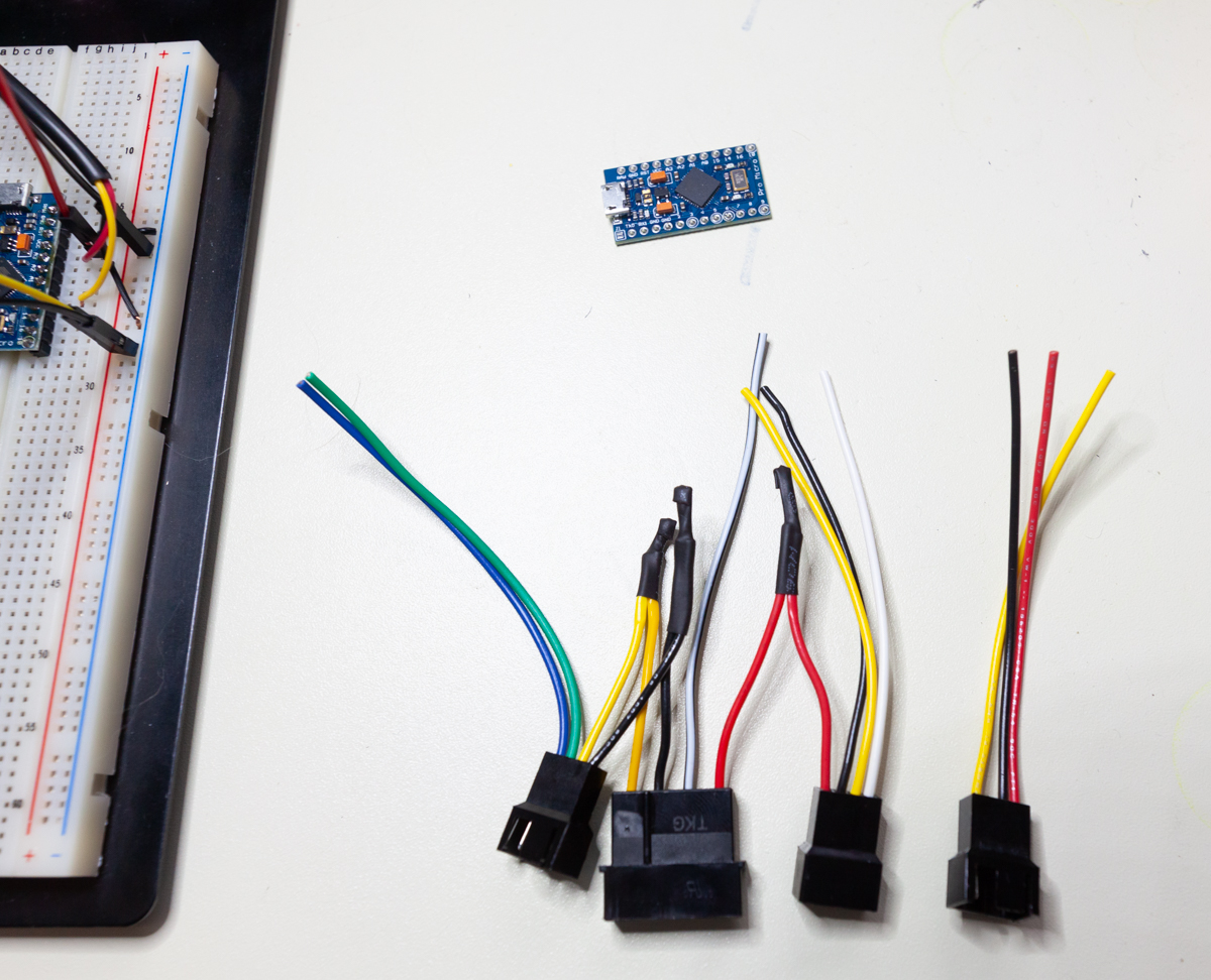
Here's a few photos of the Arduino all soldered together. When I put it in the case, I slide a big heat-shrink tube around it to keep stuff from shorting out on the chassis, etc.
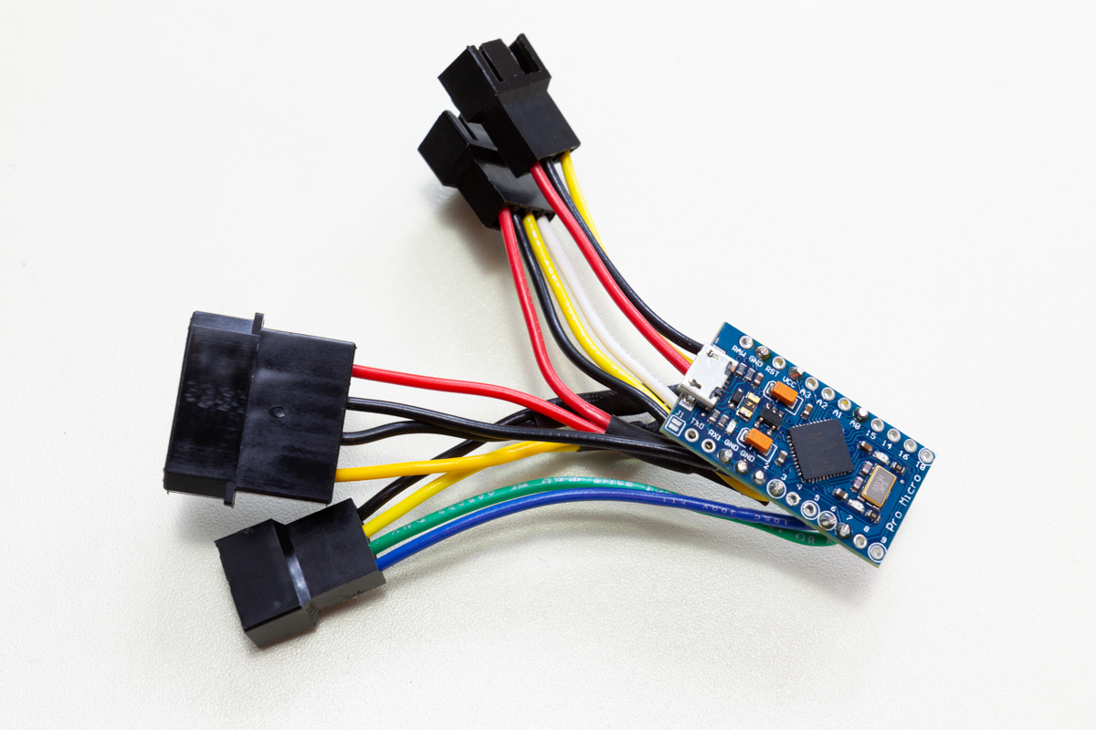
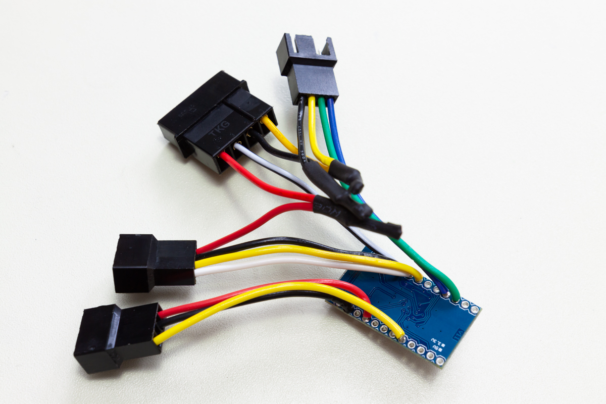
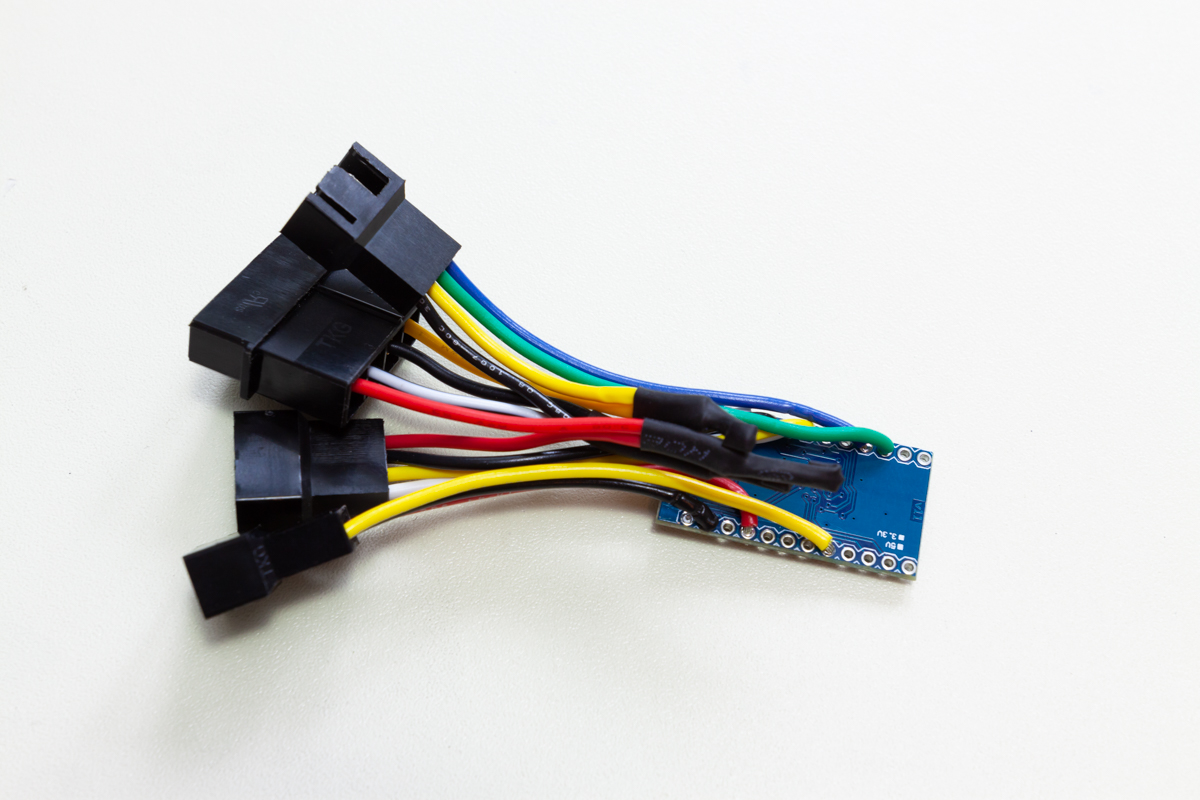
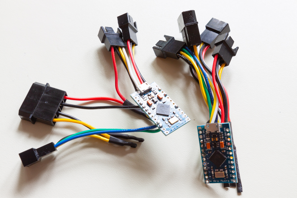
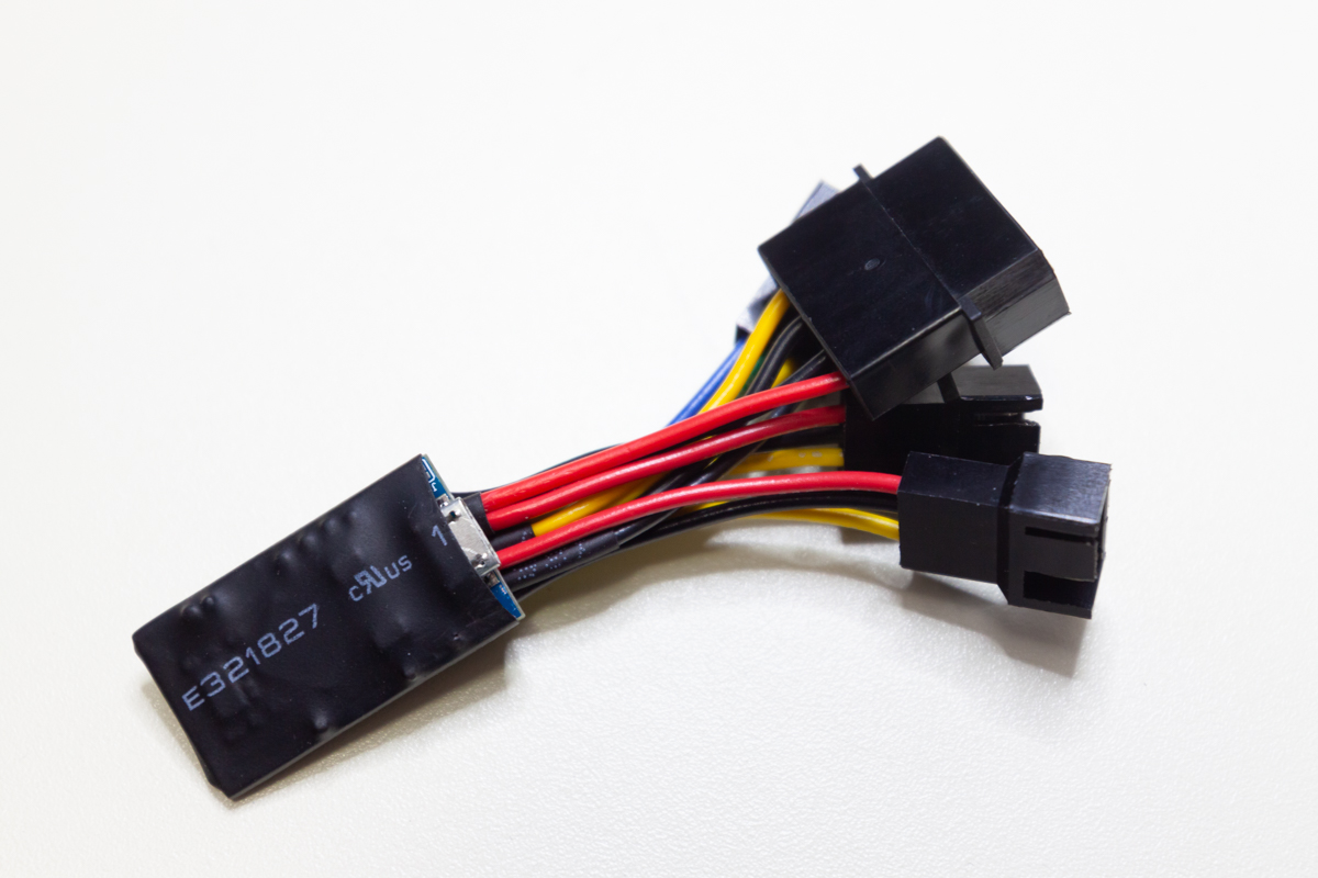
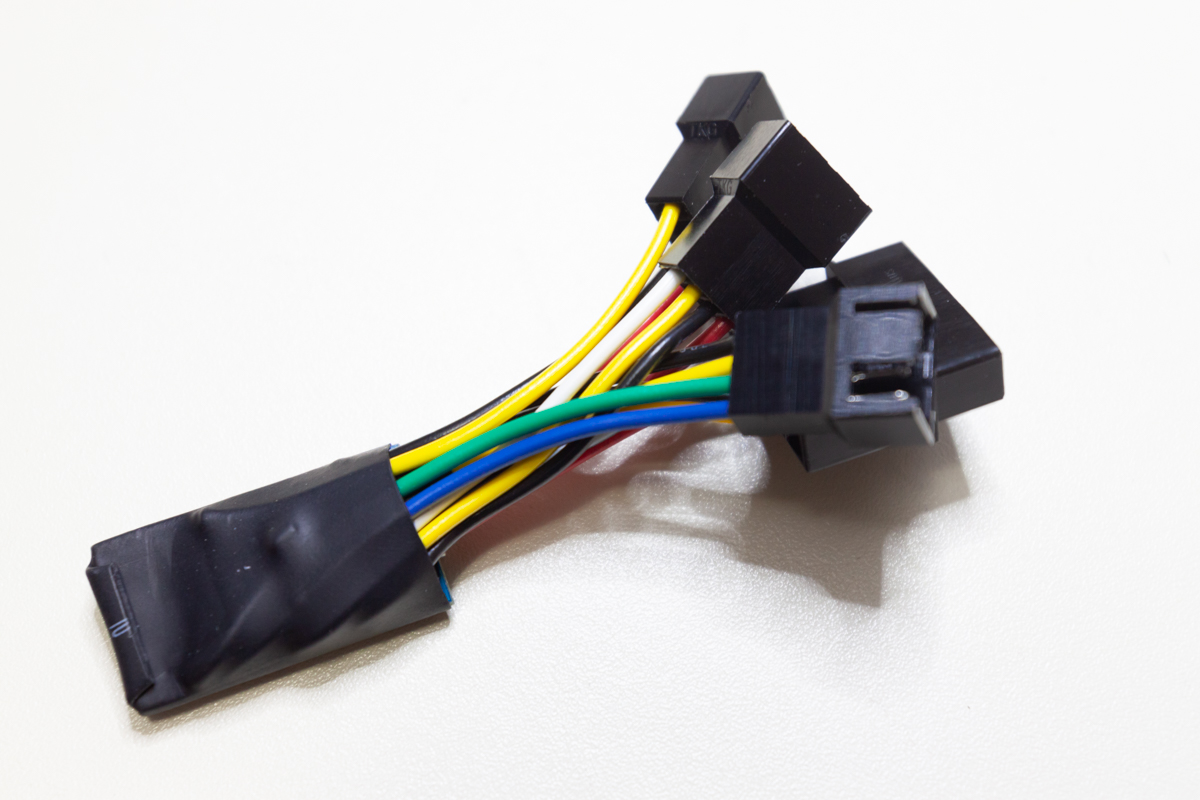
The photos below show the I2C display I used, first in testing, then in its 3D printed mount that was secured with Velcro to the top of each chassis.
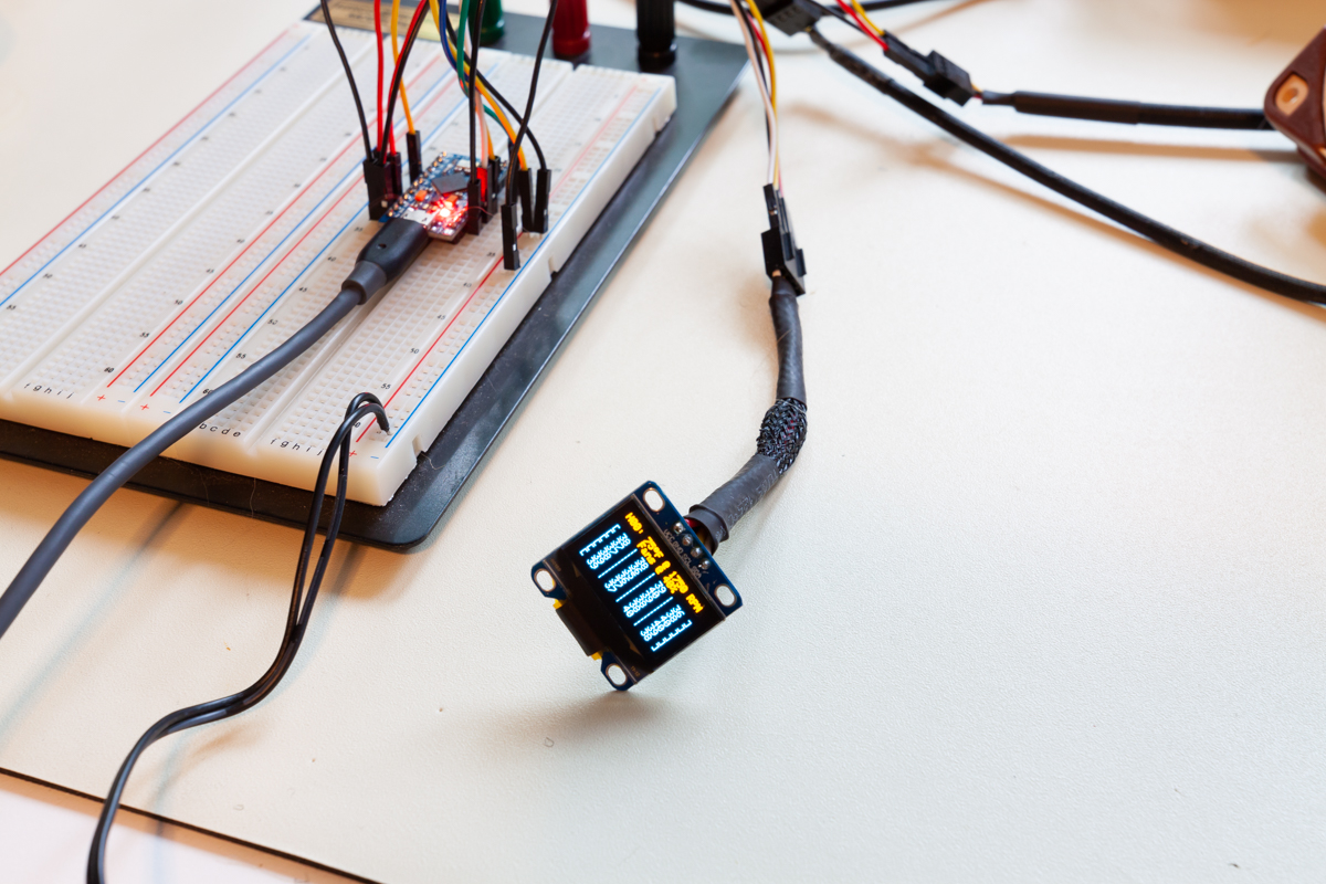
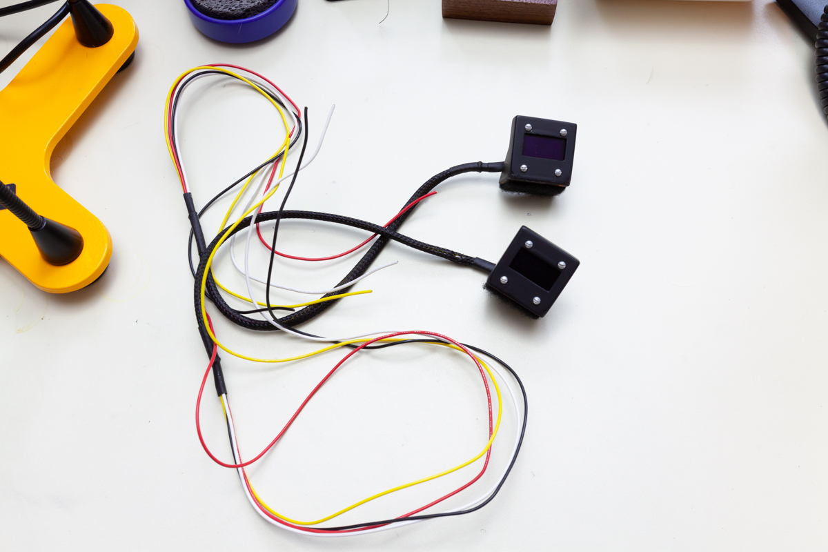
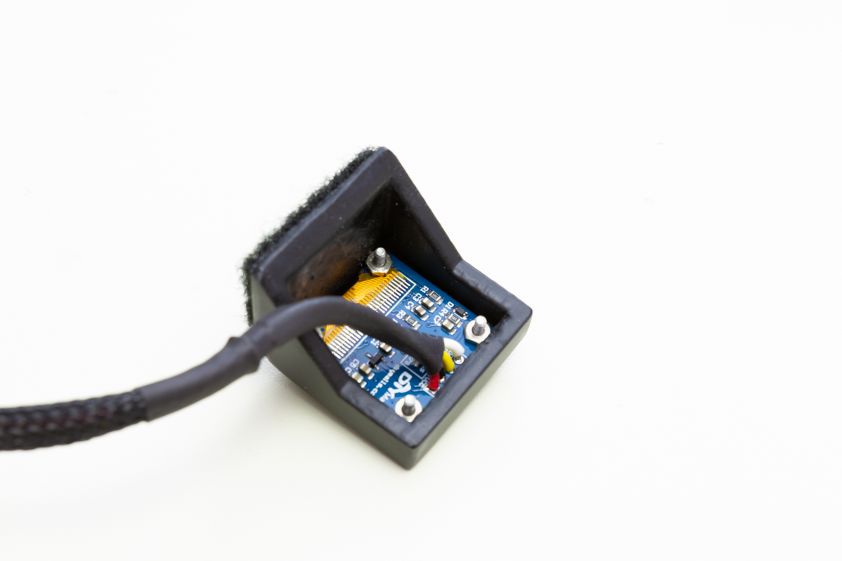
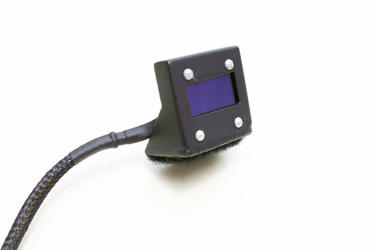
All of this worked fairly well, but the 1" displays was so small that the text was almost impossible to read unless you were right up in front of it. I also had issues with one of the displays where the text would wrap around to the bottom of the display every so often, likely due to RF interference or clock skew or something. I never did figure out what was causing it.
I ran this setup for a week or so and pretty quickly came upon some major issues. The Arduinos would freeze up every so often and I would have to reset them by power cycling them. When they locked up, the tiny OLED display and (more importantly) the fans’ duty cycles wouldn't update. The first time this happened, I didn't catch it until the drives were very hot, some close to 50 degrees C.
To make it so I didn't have to keep manually power cycling the Arduinos, I added an automatic reset function to the fan control script. The Arduinos I used have a feature where if you open a serial connection with them at 1600 baud and then drop that connection, the microcontroller will reset itself. In the script, I added a check that ran every 60 seconds which asked the Arduinos to ID themselves (just like I did at the beginning of the script). If the Arduino was locked up, it wouldn't respond to the ID request. As before, I had to run the ID request command in a loop and count the number of iterations before it bailed and reset the Arduino (I had it set at 20 attempts). With this automatic reset function in place, the whole setup was a lot more robust. I ran this setup for several more weeks and it did alright, but the Arduinos seemed to reset themselves far too often; typically five or six times per day. When the Arduinos reset, the fans would all suddenly ramp up to 100% and stay there for 30 to 60 seconds until they got the duty cycle command from the fan control script. This ended up being very annoying; I tried using much shorter USB cables to connect the Arduinos thinking that the 8' cable was losing too much signal. I also added ferrite cores to the USB cables to try to cut down on noise. These did make an improvement, but the Arduinos were still resetting several times a day.
After a few more weeks of sitting in a room with fans that would randomly ramp up to 3000 RPM and then spin themselves back down, I got so frustrated that I decided to scrap the whole Arduino approach and re-implement everything on Raspberry Pis. Of course the Pi is massive overkill for a project like this, but I wanted something more reliable than the serial connection on the Arduino. I probably could have gotten things working much more reliably on the Arduinos by doing more troubleshooting, but I was way too frustrated with them at that point, and I was also intrigued by the enhanced capabilities of moving all the communications to Ethernet. I could get rid of the little I2C displays and instead set up a simple web server to display all the system vitals. I could have it displayed on a much larger (but still fairly small) screen with much more information and I could also of course access that web server from any other device I wanted.
I started by porting the Arduino C code to Python to run on the Raspberry Pis, which would let them generate the necessary PWM signal to control the fans as well as measure the fan speed and ambient temperature in the chassis. Instead of receiving commands via serial, the Pi's are connected via Ethernet and use Python's socket module to receive commands from the FreeNAS system. And instead of displaying the system statistics on attached I2C panels, the script sends all the data to another Raspberry Pi running flask, socket.io, and redis which formats and displays everything on a live web page. I have the web page displayed on a dedicated 1080p 11" touchscreen I got from a Chinese retailer. The fan speed, duty cycle, and ambient temperature information is sent by the two Raspberry Pi fan controllers, while the FreeNAS system itself sends the individual drive temperatures to the display controller Pi, also via python sockets. With the increased resolution of the 11" display, I can also show some extra information like the FreeNAS system's CPU temperatures, the CPU cooler’s fan speeds and duty cycles, and the average CPU load.
The bare Raspberry Pi and wire harness are picked below (attached via a ribbon cable). Since I'm using a separate unit to display system statistics, I didn't need a plug for the display on the Pi.
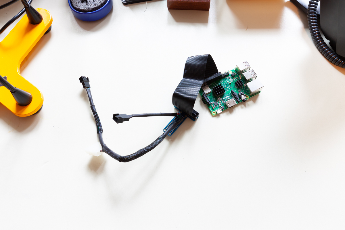
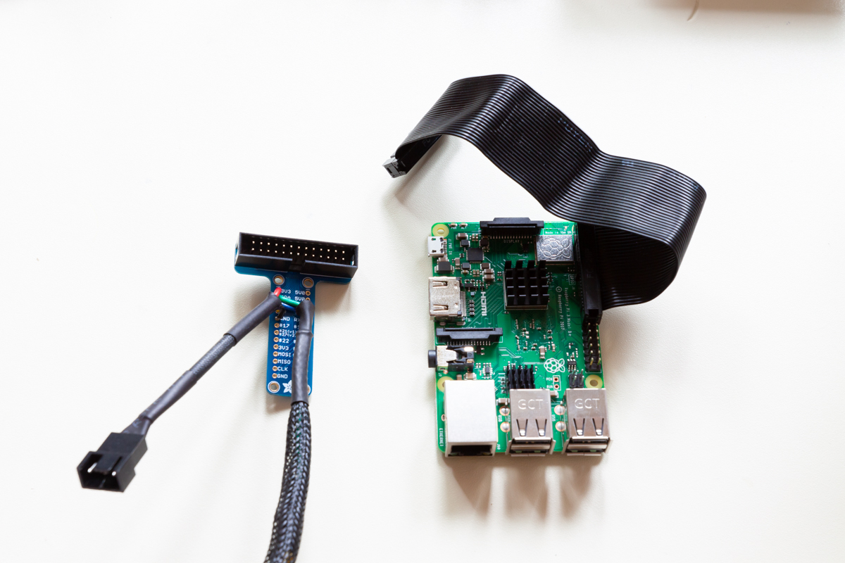
The Pi's wiring has a connection for the fans (top left), a 4-pin MOLEX for extra power (lower left), and for the thermal probe (center).
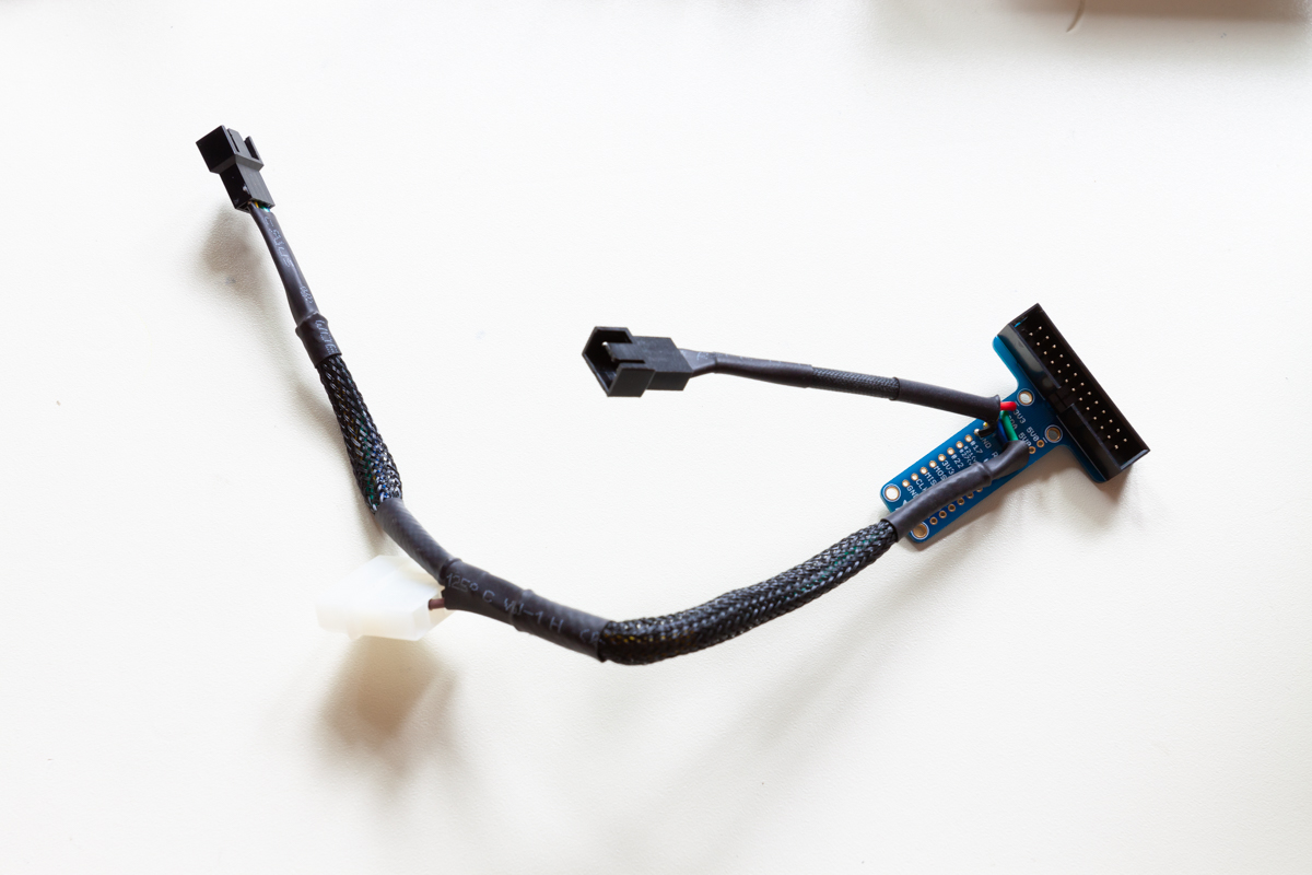
Without the cable jacket, you can get a better idea of how everything is wired.
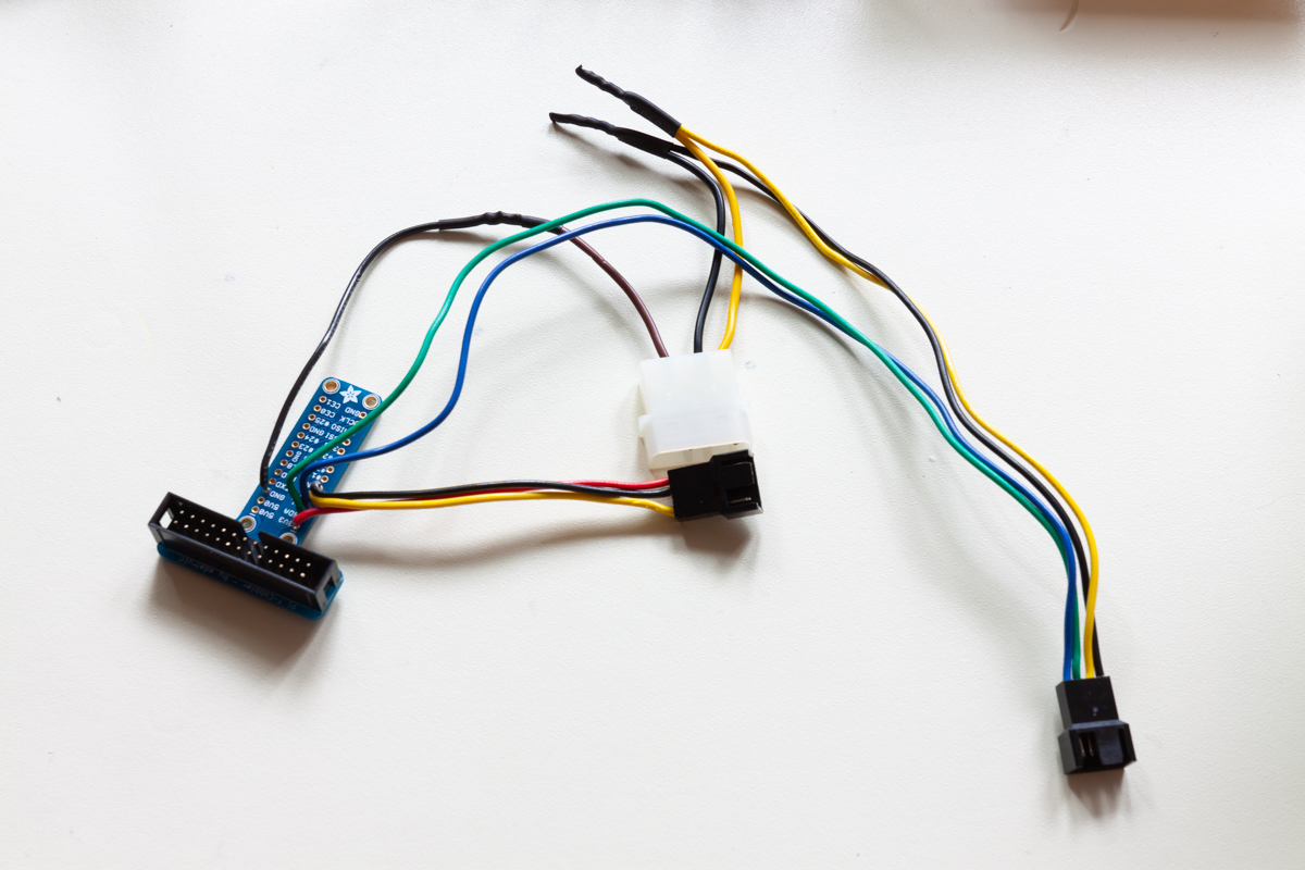
These photos show the Pis installed inside of each chassis.
These photos show the display console output.
Final Results and Future Plans
The system has been running on this raspberry pi setup for several months now and has been pretty much rock solid. The scripts are set up to gracefully handle socket disconnection and continue running while attempting to reconnect. There are a few other modifications and improvements I have planned, including better threading on the fan controller pis, more robust socket reconnection logic between all parts of the system, buttons on the display web page to control variables like ramp speed and duty cycle mappings, the Raspberry Pi's vitals, and some additional statistics from the FreeNAS system like pool capacity. I’d also like to have it display data from other systems in my lab, like my primary workstation and FreeNAS Mini. The source code for everything is still in a pretty rough state and it's obviously very specific to my setup, but I do have everything in a Github repository here if you’re curious to look through it.
Once the new shelf was in and working, I added 16 new 8 TB drives to the system, so the usable storage capacity has increased from about 100 TB to about 180 TB and I still have room in the shelf for another 8 drives. I also added more RAM to the system (which now totals 128 GB) and got that Optane 900p drive I mentioned before to use as an L2ARC. And finally, I added cable management arms to all the chassis. For some reason, Supermicro doesn’t make arms for the 846, but their 2U/4U arm worked after doing a little bit of cutting on one of the included brackets.
With the added fans, the noise level in my office has definitely gone up a little bit, but I've found that the fans in the expansion shelf are almost always at 25-30%, or like 800-1000 RPM. I do still plan on finding a spot outside my office for the rack, but that's at least several years off. With the additional vdevs in my FreeNAS system, performance has also increased. I'm able to get 650-700 MB/s sequential reads and writes between the FreeNAS and my workstation, but I think I can do some samba tuning to increase that to 1 GB/s. Note that if you do a similar expansion, you may want to manually re-balance your vdevs by moving all your data into another temporary dataset, then moving it all back into the primary dataset. This ensures that the data is evenly distributed across all vdevs and reads and writes can be equally divided between all the drives.
Looking back on this update, I definitely took a more difficult route to achieve storage expansion, but I had a lot of fun planning, developing, and implementing everything. The fan control was obviously the biggest hurdle and could have been avoided completely if I had this system in a room where noise wasn't an issue (like by just letting the fans run at full speed). If you don’t have to worry about fan control, FreeNAS expansion is pretty simple. Enterprise storage systems like TrueNAS use more advanced expansion shelves with an integrated baseboard management controller (or BMC), often with its own web UI and fan control based on temperature sensors around the chassis. The shelf’s BMC doesn’t have access to the drives' internal temperatures though, so the fan control isn’t quite as tight as my setup.
That being said, these enterprise storage systems are scaled up in the exact same way we just covered, sometimes to 10’s of petabytes. For maximum density, they can use top-loading expansion shelves with sometimes over 100 drive bays in a 4U chassis. On the opposite end of the spectrum, it would be easy enough for a home lab user to buy a second mid-tower case, stuff it full of drives, rig the PSUs together, and connect the expansion tower with an external SAS cable.
Closing and Summary
If you’ve been following along, you should now have a pretty robust file server configured. It should be able to tolerate the failure of one or more hard drives, automatically report on low-level disk and pool errors before they cause hardware failures, heal minor boot and data pool errors, adjust fan speed to keep itself cool, shut itself down gracefully when it loses wall power, back up its configuration files on a regular basis, back up all its user data to the cloud, and run any sort of Linux-based VM you might require for other tasks! Hopefully you’ve learned a few things as well. I happily welcome any feedback you might have on this write up; please let me know if you spot any mistakes, misconceptions, sections that aren’t very clear, or a task that can be tackled in an easier manner. Thank you for reading, and feel free to contact me with questions and comments, or if you're interested in having me build a similar system for you: jason@jro.io!